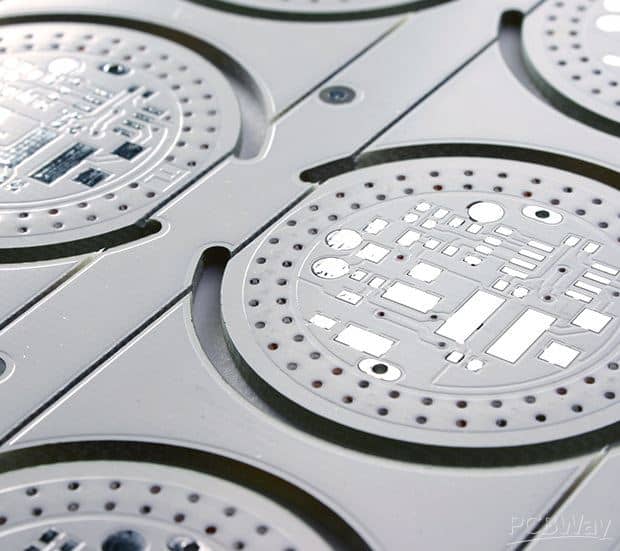
Aluminum printed circuit boards (PCBs) are circuit boards made with aluminum as the base substrate material instead of the more common FR-4 glass epoxy. Aluminum PCBs provide several advantages over traditional FR-4 PCBs but also have some unique design considerations.
Benefits of Aluminum PCBs
Superior Thermal Performance
Aluminum has excellent thermal conductivity, nearly 100 times greater than FR-4. This allows aluminum PCBs to dissipate heat extremely effectively from heat generating components. This makes aluminum PCBs ideal for designs with high power electronics, LEDs, power converters and amplifiers.
The improved thermal performance of aluminum PCBs results in:
- Lower component operating temperatures
- Increased reliability and lifetime of electronics
- Ability to use higher power components without overheating
- Elimination or reduction of secondary heat sinks
Lightweight
Aluminum has a density of 2.7 g/cm^3 compared to 1.9 g/cm^3 for FR-4. This makes aluminum PCBs lighter by 30-50% compared to an FR-4 board of the same size. The lightweight nature of aluminum PCBs makes them suitable for weight sensitive aerospace, automotive and consumer electronics applications.
High Strength and Flatness
Aluminum PCB substrates can be made from high strength alloys which resist warping and bending much better than FR-4. This means aluminum boards can be made thinner while maintaining stiffness required for manufacturing and assembly. It also results in better flatness for optimal thermal contact with heat spreaders and sinks.
Thinner aluminum PCBs translate to:
- Reduced product weight and size
- Compact, space saving PCB designs
- Low profile assemblies
Corrosion Resistance
Aluminum forms an impervious oxide layer when exposed to air. This makes aluminum highly corrosion resistant, protecting it from environmental degradation over the lifetime of a product. Aluminum PCBs can be used in humid, salty and other harsh environments where uncoated copper would oxidize.
Design Flexibility
Aluminum PCBs facilitate design innovation and flexibility due to the combination of thermal, mechanical and electrical properties. For example, aluminum can be used as a heat sink, structural component and circuit board – simplifying and consolidating parts.
Aluminum also enables integration of lead frame, thermal plane and dielectric layers into a single unified design and fabrication process. This opens new possibilities for miniaturization, thermal management and robustness.
Cost Savings
By reducing overall system size, weight and parts count, aluminum PCBs can provide significant lifetime cost savings over conventional solutions. This is especially noticeable in industries like aerospace where reduced weight has multiplicative savings from fuel efficiency over thousands of flights.
The excellent thermal performance of aluminum PCBs also allows using fewer or lower cost heatsinks and heat spreaders.
Challenges with Aluminum PCBs
While aluminum PCBs have many benefits, they also come with some unique design and manufacturing challenges:
Thermal Expansion
Aluminum has a coefficient of thermal expansion (CTE) of 23 ppm/K compared to 17 ppm/K for FR-4. This higher rate of expansion and contraction under temperature changes needs to be considered in design to avoid mechanical stresses.
strategeies to account for CTE mismatch include:
- Use of solder joints rather than press fit connections
- Minimal or no hard board-to-board connections
- Careful component placement to minimize thermal gradients
Thermal Conductivity
The high thermal conductivity of aluminum can be a double edged sword. While beneficial for heat removal, it also makes localized heating more difficult. Techniques like thick copper planes and thermal reliefs may be needed for trace routing and soldering.
Surface Oxidation
The oxidation layer on aluminum surfaces increases contact resistance and makes soldering more difficult. Special surface treatments or preparation is required for successful solder joint formation and wire bonding.
Material Cost
Raw aluminum is cheaper than FR-4 but processing costs are higher. Electroplating to form conductive traces also adds cost compared to copper clad FR-4. Overall aluminum PCB cost can be 20-50% more than FR-4.
Supply Chain Maturity
The aluminum PCB industry currently has fewer manufacturers and higher lead times compared to traditional FR-4 PCBs. The design expertise and supply chain is less mature although growing rapidly.
Aluminum PCB Materials
Aluminum PCB substrates are made from aluminum alloys rather than pure aluminum. Different alloys offer various advantages:
Alloy Series Typical Properties
Table of common aluminum PCB alloys
| Alloy Series | Benefits |
|---|---|
| 1000 | Excellent corrosion resistance, low cost |
| 5000 | High strength, good corrosion resistance |
| 6000 | High strength, good formability |
| 7000 | Highest strength, suitable for very thin PCBs |
Dielectric Films
The aluminum core is coated with dielectric films on one or both sides to isolate it from the conductive copper traces. Common dielectric films include:
- Polyimide: High thermal stability, widely used for flex PCBs
- FR-4: Most cost effective, not suitable for high temp operation
- PTFE: Extremely high working temp up to 600°F
Copper Foil
Copper foil is laminated onto the dielectric to form the conductive layer for traces, pads and planes. Standard electrodeposited copper foils with thickness of 0.5-2 oz (18-70 μm) are typically used.
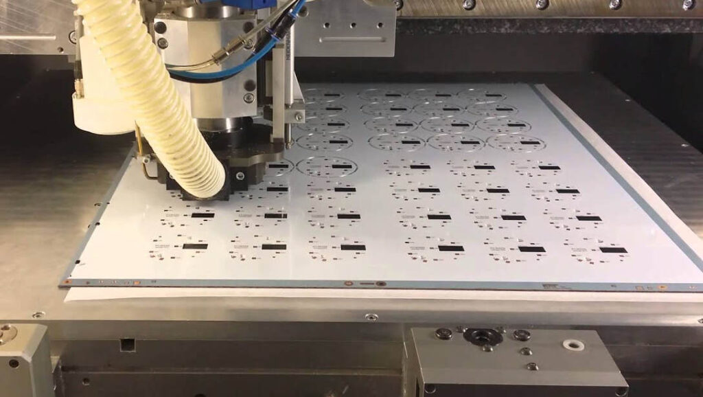
Aluminum PCB Fabrication
Aluminum PCBs require specialized fabrication processes tailored to the unique material properties.
Panel Plating
Traces and pads are formed by electroplating copper onto the dielectric surfaced aluminum panels. Photoresist patterning similar to PCB fabrication is used to selectively plate the circuit pattern.
Surface Treatments
A chemical conversion coating is applied to aluminum surfaces to improve adhesion and create a solderable surface. Zincate treatment is commonly used.
Dielectric Bonding
Dielectric films are bonded to the aluminum under high temperature and pressure. Specialized thermocompression processes are used to achieve strong adhesion.
Patterning and Etching
Laser ablation can be used to selectively remove aluminum for creating cavities, heatsink areas and complex 3D structures. Photochemical etching techniques are also used.
Via Formation
Laser drilling is primarily used for forming thru hole vias. This avoids the smearing and debris caused by mechanical drilling in soft aluminum.
Solder Mask
A solder mask coating is applied for environmental protection and preventing solder bridging. Epoxy or polyimide solder resists withstand aluminum PCB operating temperatures.
Design Rules for Aluminum PCBs
Aluminum PCBs have different design constraints than standard FR-4 which designers should be aware of:
- Trace width/spacing: Similar to FR-4 but increased spacing helps minimize CTE related stresses.
- Hole size: Lasers allow smaller vias than with FR-4, down to 0.15mm.
- Hole spacing: Closer spacing possible but thermal expansion effects on reliability should be considered.
- Finished thickness: Can be made thinner than FR-4 for lightweight designs, flexibilty.
- Edge spacing: Increased clearance to avoid shorting and plasma etching undercutting.
- Solder mask expansion: Larger expansion helps account for greater CTE compared to FR-4.
- Thermal relief: Used extensively to control heating of traces and prevent lifting during soldering.
- Plane layers: Can serve simultaneously as thermal sink so optimal placement is critical.
Smart layout and placement techniques on aluminum PCBs minimize problems from CTE mismatch, thermal conductivity, soldering and other factors.
Applications of Aluminum PCBs
Some examples of products and applications using aluminum PCB technology:
- LED lighting – High brightness LEDs require excellent thermal management. Aluminum PCBs keep LED junction temperatures low for bright, reliable operation. They also allow flexible luminaires and fixtures not achievable with metal core PCBs.
- Electric vehicles – Power electronics for electric drivetrains generate significant heat which aluminum PCBs can effectively dissipate in a lightweight, compact and robust package.
- Power supplies – Switching power supplies efficiency and power density improves with better thermal performance. Aluminum PCBs allow higher frequency, higher efficiency power supply modules.
- Aerospace – Avionics, guidance systems and other electronics benefit from the reduced weight and resistance to vibration, shock and extreme temperatures provided by aluminum PCBs.
- 5G telecom – The high bandwidth 5G NR systems rely on power amplifiers, diplexers, antennas and other RF circuits which aluminum PCB technology greatly aids through heat dissipation, precision and stability.
Aluminum PCBs continue finding broader applicability as the technology matures. Their unique thermal, mechanical and electrical properties provide new design opportunities not possible with conventional PCB materials.
Aluminum PCB FQA
Is aluminum PCB better than FR4?
In many high power, high frequency and demanding applications aluminum PCBs offer substantial benefits over FR4. The thermal conductivity of aluminum is far superior to FR4, allowing better cooling. Aluminum PCBs are also lighter while providing greater strength and flatness. The high cost of aluminum PCBs means FR4 still dominates many cost sensitive, lower performance uses.
Is aluminum PCB reliable?
Properly designed aluminum PCBs can be very reliable with lifetimes comparable or exceeding FR4 boards. Aluminum forms an impervious oxide layer providing environmental protection. The thermal expansion effects and soldering challenges of aluminum can be mitigated with suitable design techniques. Companies like Cicor offer aluminum PCBs meeting automotive quality standards.
Can you solder aluminum PCBs?
Soldering aluminum requires special pretreatments like zincate conversion coating to allow solder wetting on the oxide layer surface. Thermal reliefs and other methods also help prevent soldering damage. Aluminum PCB designers should collaborate closely with manufacture partners to ensure a solderable, manufacturable board.
What are the AL PCB design rules?
Key aluminum PCB design rules involve dealing with the coefficient of thermal expansion mismatch between components and aluminum. This includes increased spacing, solder joints vs press fit connections and minimizing thermal gradients. Aluminum PCBs also require thermal reliefs for trace routing and soldering. Working closely with manufacturers to design for their process capabilities is advised.
What are aluminum PCBs used for?
Aluminum PCBs are ideal for applications demanding high thermal performance, lightweight construction and ruggedness like LED lighting, electric vehicles, aerospace systems and high power electronics. Telecom infrastructure and small cell equipment also benefit from aluminum PCBs due to the excellent heat dissipation as wireless data rates continue increasing.


Leave a Reply