What is a Rigid-Flex PCB?
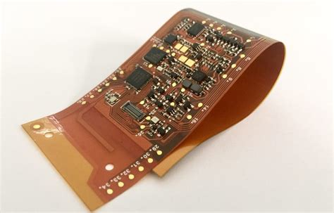
A rigid-flex PCB (printed circuit board) is a hybrid board that combines rigid and flexible substrates into a single interconnect structure. It consists of multiple layers of flexible PCB substrate integrated with rigid PCB layers. This unique configuration allows the board to be bent and folded to fit into tight, compact spaces or to flex during operation.
Rigid-flex PCBs offer several advantages over traditional rigid boards or separate rigid and flex circuits, including:
- Reduced size and weight
- Increased reliability
- Improved electrical performance
- Elimination of connectors
- Ability to withstand vibration and thermal cycling
- Streamlined assembly process
These attributes make rigid-flex PCBs well-suited for a wide range of applications, particularly in industries that require high-density interconnects in small form factors, such as aerospace, military, medical devices, consumer electronics, and automotive systems.
Rigid-Flex PCB Construction
A typical rigid-flex PCB consists of a flexible substrate, such as polyimide (PI) or polyethylene terephthalate (PET), laminated together with rigid FR-4 layers. Copper traces are etched onto the flexible layers to create the interconnects between components.
The flexible layers are typically very thin, ranging from 1-3 mils (0.025-0.075 mm), while the rigid layers are thicker, usually 20-60 mils (0.5-1.5 mm). The number of layers in a rigid-flex PCB can vary depending on the complexity of the design, but it is common to see 4-12 layer stackups.
Here is an example of a 6-layer rigid-Flex PCB Stackup:
| Layer | Material | Thickness (mils) |
|---|---|---|
| Top Cover | PI | 1 |
| Top Flex | PI + Cu | 2 |
| Rigid 1 | FR-4 + Cu | 6 |
| Rigid 2 | FR-4 + Cu | 6 |
| Bottom Flex | PI + Cu | 2 |
| Bottom Cover | PI | 1 |
The copper traces on the flexible layers are typically protected by a coverlay, which is a thin film of PI or PET that is laminated over the traces. The coverlay provides insulation and protection against damage during assembly and operation.

Rigid-Flex PCB Manufacturing Process
The manufacturing process for rigid-flex PCBs is more complex than that of standard rigid boards due to the combination of materials and the need to create a reliable interconnect between the rigid and flexible sections.
The general steps in the rigid-flex PCB manufacturing process are:
-
Design and Layout: The PCB design is created using CAD software, taking into account the specific requirements of the rigid-flex construction. The layout must consider the placement of components, the routing of traces, and the location of the flexible sections.
-
Material Selection: The appropriate materials for the rigid and flexible layers are selected based on the electrical, mechanical, and environmental requirements of the application. Common materials include FR-4 for the rigid layers and polyimide for the flexible layers.
-
Lamination: The flexible layers are laminated together with the rigid layers using heat and pressure. Special care must be taken to ensure good adhesion between the layers and to avoid delamination during the subsequent processing steps.
-
Drilling: Holes are drilled through the rigid sections of the board to accommodate through-hole components and vias. The flexible sections are not drilled at this stage.
-
Plating: The drilled holes are plated with copper to create electrical connections between the layers. A thin layer of copper is also plated onto the surface of the board to provide a solderable finish.
-
Etching: The unwanted copper is etched away, leaving the desired circuit patterns on the rigid and flexible layers.
-
Coverlay Application: The coverlay is laminated onto the flexible layers to protect the copper traces and provide insulation.
-
Solder Mask Application: A solder mask is applied to the rigid sections of the board to protect the copper traces and prevent short circuits during soldering.
-
Silk Screen Printing: Text and symbols are printed onto the surface of the board using silk screening to aid in assembly and identification of components.
-
Outline Routing: The board is cut to its final shape and size using a routing machine. The flexible sections are cut using a special blade to avoid damaging the delicate circuits.
-
Electrical Testing: The completed board is electrically tested to ensure that all connections are functioning correctly and that there are no short circuits or open connections.

Applications of Rigid-Flex PCBs
Rigid-flex PCBs are used in a wide range of applications across various industries. Some of the most common applications include:
Aerospace and Military
Rigid-flex PCBs are extensively used in aerospace and military applications due to their ability to withstand harsh environments and provide reliable performance in compact spaces. Examples include:
- Avionics systems
- Missile guidance systems
- Radar systems
- Satellite communication systems
- Unmanned aerial vehicles (UAVs)
Medical Devices
Rigid-flex PCBs are increasingly used in medical devices due to their ability to provide high-density interconnects in small, lightweight packages. Examples include:
- Implantable devices such as pacemakers and defibrillators
- Wearable devices such as health monitors and drug delivery systems
- Surgical instruments such as endoscopes and catheters
- Diagnostic equipment such as ultrasound and X-ray machines
Consumer Electronics
Rigid-flex PCBs are used in consumer electronics to enable compact, lightweight designs with high functionality. Examples include:
- Smartphones and tablets
- Wearable devices such as smartwatches and fitness trackers
- Cameras and camcorders
- Gaming systems and controllers
Automotive
Rigid-flex PCBs are used in automotive applications to provide reliable performance in harsh environments and to enable advanced features such as driver assistance and infotainment systems. Examples include:
- Engine control units (ECUs)
- Transmission control modules (TCMs)
- Adaptive cruise control systems
- Infotainment systems
- Advanced driver assistance systems (ADAS)

Frequently Asked Questions (FAQ)
1. What are the advantages of rigid-flex PCBs over traditional rigid boards?
Rigid-flex PCBs offer several advantages over traditional rigid boards, including:
- Reduced size and weight: Rigid-flex PCBs can be folded and bent to fit into tight spaces, enabling more compact designs.
- Increased reliability: By eliminating connectors and reducing the number of solder joints, rigid-flex PCBs are more reliable than separate rigid and flex circuits.
- Improved electrical performance: The integrated design of rigid-flex PCBs reduces signal loss and improves signal integrity compared to separate boards.
- Streamlined assembly: Rigid-flex PCBs simplify the assembly process by reducing the number of components and connections required.
2. What materials are commonly used in rigid-flex PCBs?
The most common materials used in rigid-flex PCBs are:
- FR-4: A glass-reinforced epoxy laminate used for the rigid layers.
- Polyimide (PI): A flexible polymer used for the flexible layers and coverlay.
- Copper: Used for the conductive traces and vias.
3. How many layers can a rigid-flex PCB have?
The number of layers in a rigid-flex PCB can vary depending on the complexity of the design, but it is common to see 4-12 layer stackups. Some advanced designs may have up to 20 or more layers.
4. What are the challenges in manufacturing rigid-flex PCBs?
Some of the main challenges in manufacturing rigid-flex PCBs include:
- Ensuring good adhesion between the rigid and flexible layers to prevent delamination.
- Maintaining the integrity of the flexible layers during the drilling and plating processes.
- Achieving proper alignment of the layers during lamination.
- Handling and processing the thin, delicate flexible layers without damage.
5. How do rigid-flex PCBs compare in cost to traditional rigid boards?
Rigid-flex PCBs are generally more expensive than traditional rigid boards due to the more complex manufacturing process and the use of specialized materials. However, the higher upfront cost can often be offset by the reduced assembly time and improved reliability in the end application.
Conclusion
Rigid-flex PCBs offer a unique solution for applications that require high-density interconnects in compact, lightweight packages. By combining the advantages of rigid and flexible substrates, rigid-flex PCBs enable designers to create products with improved functionality, reliability, and performance.
While the manufacturing process for rigid-flex PCBs is more complex than that of traditional rigid boards, the benefits in terms of size, weight, and reliability make them an attractive option for a wide range of industries, including aerospace, military, medical devices, consumer electronics, and automotive.
As technology continues to advance and the demand for smaller, more capable devices grows, rigid-flex PCBs will likely play an increasingly important role in the electronics industry, enabling the next generation of innovative products and systems.


Leave a Reply