Introduction to IC7447
The IC7447 is a BCD to seven-segment decoder/driver integrated circuit that is commonly used in electronic displays. It is designed to convert a binary-coded decimal (BCD) input into the appropriate signals to drive a seven-segment LED or LCD display. This guide will provide a comprehensive overview of the IC7447, including its features, pinout, functionality, and practical applications.
What is a BCD to Seven-Segment Decoder/Driver?
A BCD to seven-segment decoder/driver is an electronic circuit that takes a BCD input and converts it into the signals needed to display the corresponding decimal digit on a seven-segment display. BCD is a digital encoding scheme where each decimal digit is represented by a four-bit binary code. The IC7447 is specifically designed to perform this conversion and drive the display directly.
Features of the IC7447
The IC7447 offers several key features that make it a popular choice for driving seven-segment displays:
- BCD input compatibility
- Active-low outputs for directly driving common cathode displays
- Ripple blanking input for leading/trailing zero suppression
- Lamp test input for testing all segments simultaneously
- Low power consumption
- Wide supply voltage range (4.5V to 15V)
Understanding the IC7447 Pinout
To effectively use the IC7447, it is essential to understand its pinout and the function of each pin. The IC7447 is available in a 16-pin DIP (Dual Inline Package) format. The following table provides a description of each pin:
| Pin Number | Pin Name | Description |
|---|---|---|
| 1 | B | BCD input B |
| 2 | C | BCD input C |
| 3 | LT | Lamp Test input (active low) |
| 4 | BI/RBO | Blanking Input/Ripple Blanking Output |
| 5 | RBI | Ripple Blanking Input |
| 6 | D | BCD input D |
| 7 | A | BCD input A |
| 8 | GND | Ground |
| 9 | e | Segment e output |
| 10 | d | Segment d output |
| 11 | c | Segment c output |
| 12 | b | Segment b output |
| 13 | a | Segment a output |
| 14 | g | Segment g output |
| 15 | f | Segment f output |
| 16 | VCC | Power supply voltage |
BCD Inputs (A, B, C, D)
The IC7447 accepts a 4-bit BCD input through pins A, B, C, and D. These inputs represent the decimal digit to be displayed on the seven-segment display. The following table shows the BCD codes and their corresponding decimal digits:
| BCD Input (DCBA) | Decimal Digit |
|---|---|
| 0000 | 0 |
| 0001 | 1 |
| 0010 | 2 |
| 0011 | 3 |
| 0100 | 4 |
| 0101 | 5 |
| 0110 | 6 |
| 0111 | 7 |
| 1000 | 8 |
| 1001 | 9 |
| 1010 to 1111 | Not used |
Segment Outputs (a, b, c, d, e, f, g)
The IC7447 provides seven active-low output pins (a, b, c, d, e, f, g) that correspond to the individual segments of a seven-segment display. When a segment output is low (0), the corresponding segment on the display will illuminate. The following diagram illustrates the arrangement of the segments on a typical seven-segment display:
   a
f     b
   g
e     c
   d
Lamp Test Input (LT)
The Lamp Test input (pin 3) is an active-low input that, when pulled low, causes all segment outputs to go low, illuminating all segments on the display simultaneously. This feature is useful for testing the display and ensuring that all segments are functioning correctly.
Blanking Input/Ripple Blanking Output (BI/RBO) and Ripple Blanking Input (RBI)
The Blanking Input/Ripple Blanking Output (BI/RBO) and Ripple Blanking Input (RBI) pins are used for leading/trailing zero suppression in multi-digit displays. When the BI/RBO pin is pulled low, the segment outputs will be forced high (display blanked) if the BCD input is zero and the RBI pin is also low. This allows for the suppression of leading zeros in a multi-digit display.
The RBI pin is typically connected to the BI/RBO pin of the next most significant digit’s IC7447. This creates a ripple effect, ensuring that all leading zeros are suppressed.

Interfacing the IC7447 with a Seven-Segment Display
To interface the IC7447 with a common cathode seven-segment display, follow these steps:
- Connect the segment outputs (a, b, c, d, e, f, g) of the IC7447 to the corresponding segment pins on the seven-segment display.
- Connect the common cathode pin of the seven-segment display to ground.
- Apply the appropriate BCD input to the IC7447’s A, B, C, and D pins.
- Connect the LT pin to VCC (or leave it unconnected) for normal operation, or pull it low to test all segments.
- If using multiple IC7447s for a multi-digit display, connect the BI/RBO pin of the least significant digit’s IC7447 to ground, and connect the RBI pin of each subsequent IC7447 to the BI/RBO pin of the previous IC7447.
- Apply power to the VCC pin and ground the GND pin.

Example Application: Simple BCD to Seven-Segment Display
Here’s a simple example application that demonstrates how to use the IC7447 to drive a single seven-segment display based on a BCD input:
       VCC
        |
        |
       ---
     3 | LT  VCC
       |       |
 BCD   |       |
Input  |       |
 A --7-|A      |
 B --1-|B      |
 C --2-|C      |-16---VCC
 D --6-|D  7447|
       |       |
       |       |
       ---     |
        |      |
        |      |
        8 GND  |
              ---        a
        |     |9--------/\-----
        |     |10-------|\-----
        |     |11-------\/-----    Seven
        |     |12-------/\-----   Segment
        |     |13-------|\-----    Display
        |     |14-------\/-----   (Common Cathode)
        |     |15-------/\-----
        |               |\-----
        |                     |
        |                    ---
       ---                    -
        -
       GND
In this example, the BCD input is directly connected to the A, B, C, and D pins of the IC7447. The segment outputs (a, b, c, d, e, f, g) are connected to the corresponding segments of the seven-segment display. The common cathode of the display is connected to ground. The LT pin is connected to VCC for normal operation. When a valid BCD input is applied, the corresponding decimal digit will be displayed on the seven-segment display.

Troubleshooting Tips
If you encounter issues while using the IC7447, consider the following troubleshooting tips:
- Double-check the pinout and ensure that all connections are correct and secure.
- Verify that the power supply voltage is within the specified range (4.5V to 15V).
- Ensure that the BCD input is valid and does not exceed the maximum value of 9 (1001 in BCD).
- Check the seven-segment display for any damaged or malfunctioning segments.
- Use the Lamp Test input to verify that all segments are functioning correctly.
- If using multiple IC7447s for a multi-digit display, ensure that the BI/RBO and RBI pins are connected properly for leading zero suppression.
FAQ
1. What is the purpose of the IC7447?
The IC7447 is a BCD to seven-segment decoder/driver integrated circuit. Its main purpose is to convert a 4-bit BCD input into the appropriate signals to drive a seven-segment LED or LCD display, allowing the display of decimal digits.
2. What is the maximum supply voltage for the IC7447?
The IC7447 can operate with a supply voltage range of 4.5V to 15V. It is important to ensure that the power supply voltage does not exceed 15V to avoid damaging the device.
3. How do I suppress leading zeros in a multi-digit display using IC7447s?
To suppress leading zeros in a multi-digit display using IC7447s, connect the BI/RBO pin of the least significant digit’s IC7447 to ground, and connect the RBI pin of each subsequent IC7447 to the BI/RBO pin of the previous IC7447. This creates a ripple effect, ensuring that all leading zeros are suppressed.
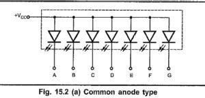
4. Can the IC7447 drive a common anode seven-segment display?
No, the IC7447 is designed to drive common cathode seven-segment displays. The segment outputs of the IC7447 are active-low, meaning they sink current to illuminate the segments. To drive a common anode display, you would need to use a different decoder/driver IC or additional circuitry to invert the outputs.
5. What should I do if the seven-segment display does not show the correct digit?
If the seven-segment display does not show the correct digit, first verify that the BCD input is valid and corresponds to the desired decimal digit. Double-check the connections between the IC7447 and the display to ensure they are correct and secure. If the issue persists, use the Lamp Test input to check if all segments are functioning properly. If one or more segments do not illuminate during the Lamp Test, the display may be damaged or malfunctioning.
Conclusion
The IC7447 is a versatile and widely used integrated circuit for driving seven-segment displays. Its ability to convert BCD inputs into the appropriate segment signals simplifies the process of displaying decimal digits on LED or LCD displays. By understanding the pinout, functionality, and interfacing techniques, beginners can effectively utilize the IC7447 in their electronic projects. This comprehensive guide has provided a solid foundation for working with the IC7447 and troubleshooting common issues.
As you continue to explore the world of electronics and display technology, the IC7447 will prove to be a valuable tool in your arsenal. Its simplicity and reliability make it an excellent choice for a wide range of applications, from simple single-digit displays to more complex multi-digit interfaces. By mastering the IC7447, you’ll be well-equipped to tackle various display-related challenges and create innovative projects that showcase your skills and creativity.


Leave a Reply