Introduction to SMT Soldering
Surface mount technology (SMT) has revolutionized the electronics manufacturing industry since its introduction in the 1960s. SMT soldering involves attaching surface-mount components directly onto the surface of a printed circuit board (PCB), as opposed to through-hole soldering where component leads are inserted into holes drilled in the PCB. SMT allows for the production of smaller, more compact electronic devices with increased functionality and reliability.
In this comprehensive guide, we will delve into the various aspects of SMT soldering, including the equipment, techniques, and best practices to achieve high-quality solder joints.
SMT Soldering Equipment
To perform SMT soldering effectively, you will need the following equipment:
- Soldering station with temperature control
- Fine-tipped soldering iron (usually between 0.2mm to 0.5mm)
- Solder wire (lead-free or leaded, depending on the application)
- Tweezers for handling small components
- Flux (liquid or paste)
- Solder wick or Desoldering Braid for removing excess solder
- Isopropyl alcohol and cleaning swabs for post-soldering cleanup
- Magnifying glass or microscope for inspection

Types of Surface Mount Components
Surface mount components come in various package types and sizes. Some common SMT component packages include:
| Package Type | Description | Example Components |
|---|---|---|
| Chip | Rectangular with two terminals on opposite ends | Resistors, Capacitors |
| SOT | Small Outline Transistor | Transistors, Diodes |
| QFP | Quad Flat Pack with leads on all four sides | Microcontrollers, ICs |
| BGA | Ball Grid Array with solder balls underneath | High-density ICs |
Understanding the different package types is crucial for selecting the appropriate soldering technique and tools.

SMT Soldering Techniques
Hand Soldering
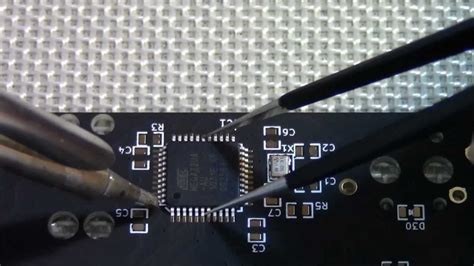
Hand soldering is the most common method for small-scale prototyping and rework. The basic steps for hand soldering SMT components are:
- Apply a small amount of solder to one of the component pads on the PCB.
- Place the component onto the PCB using tweezers, aligning it with the pads.
- While holding the component in place, touch the soldering iron tip to the component lead and the pad simultaneously. The pre-applied solder should melt and flow around the lead.
- Remove the soldering iron and let the solder joint cool and solidify.
- Repeat the process for the remaining leads.
Tips for successful hand soldering:
– Use a fine-tipped soldering iron to avoid bridging adjacent pins.
– Apply flux to the pads and leads to improve solder flow and prevent oxidation.
– Maintain the soldering iron temperature between 300°C to 350°C for lead-free solder, or 250°C to 300°C for leaded solder.
– Keep the soldering time short to prevent heat damage to the components and PCB.
Reflow Soldering
Reflow soldering is an automated process used for mass production of PCB assemblies. In this method, solder paste (a mixture of powdered solder and flux) is applied to the PCB pads using a stencil or syringe. The components are then placed onto the solder paste using a pick-and-place machine. The entire assembly is then heated in a reflow oven, which melts the solder paste and forms the solder joints.
The reflow soldering process involves four main stages:
- Preheat: The assembly is gradually heated to activate the flux and evaporate the solvents.
- Soak: The temperature is maintained just below the melting point of the solder to allow for thermal equalization.
- Reflow: The temperature is increased above the solder melting point, causing the solder to flow and form the joints.
- Cooling: The assembly is cooled down to room temperature, allowing the solder joints to solidify.
Reflow soldering requires careful control of the temperature profile to ensure proper solder joint formation and to prevent component damage.

Inspecting and Testing SMT Solder Joints
After soldering, it is essential to inspect the solder joints for quality and reliability. Visual inspection can be performed using a magnifying glass or microscope to check for the following characteristics:
- Solder joint shape: The ideal solder joint should have a concave meniscus shape, indicating good wetting of the surfaces.
- Solder Volume: Too little solder can result in a weak joint, while too much solder can cause bridging between adjacent pins.
- Solder color: A shiny, silver appearance indicates a good solder joint, while a dull or grainy appearance may suggest a poor or contaminated joint.
In addition to visual inspection, electrical testing should be performed to verify the continuity and functionality of the soldered components. This can be done using a multimeter, oscilloscope, or dedicated test fixtures.
Common SMT Soldering Defects and How to Avoid Them
- Solder Bridges: Occur when excess solder connects adjacent pins or pads.
-
Prevention: Use a fine-tipped soldering iron, apply the appropriate amount of solder, and avoid excessive heat.
-
Cold Solder Joints: Happen when the solder does not melt completely, resulting in a weak and unreliable connection.
-
Prevention: Ensure the soldering iron is at the correct temperature, and apply heat to both the pad and the component lead simultaneously.
-
Tombstoning: Occurs when one end of a component lifts off the pad due to uneven heating or surface tension.
-
Prevention: Apply solder paste evenly, ensure proper component placement, and maintain a consistent reflow temperature profile.
-
Insufficient Wetting: Happens when the solder does not adhere properly to the surfaces, resulting in a poor connection.
- Prevention: Use flux to clean and activate the surfaces, and ensure the soldering iron temperature is adequate.
Best Practices for SMT Soldering
- Always wear safety glasses and work in a well-ventilated area to protect yourself from fumes and solder splashes.
- Keep your soldering iron tip clean and tinned to ensure efficient heat transfer and prevent contamination.
- Use the appropriate solder wire diameter for the component size and pitch to avoid excess solder.
- Apply flux sparingly to prevent solder balling and bridging.
- Follow the manufacturer’s recommended temperature profiles and times for reflow soldering.
- Regularly inspect and test your solder joints to ensure quality and reliability.
- Continuously improve your skills through practice and learning from experienced professionals.
Frequently Asked Questions (FAQ)
- What is the difference between lead-free and leaded solder?
-
Lead-free solder is an alloy that does not contain lead, typically consisting of tin, silver, and copper. It has a higher melting point and requires slightly different soldering techniques compared to leaded solder. Leaded solder, on the other hand, contains a percentage of lead and has a lower melting point. The use of lead-free solder is mandated by RoHS regulations in many countries due to environmental and health concerns.
-
Can I use the same soldering iron tip for both leaded and lead-free solder?
-
It is recommended to use dedicated soldering iron tips for leaded and lead-free solder to avoid cross-contamination. Lead-free solder requires higher temperatures and can cause accelerated wear on tips used for leaded solder.
-
How do I remove excess solder from a joint?
-
Excess solder can be removed using a desoldering braid or solder wick. Place the braid onto the solder joint, apply the soldering iron to heat the braid and the joint, and the excess solder will be wicked away by the braid through capillary action.
-
What is the shelf life of solder paste?
-
Solder paste typically has a shelf life of 6 months to 1 year when stored under refrigeration (2°C to 10°C). Always check the manufacturer’s recommendations and use the paste before its expiration date to ensure optimal performance.
-
How can I improve my SMT soldering skills?
- Practice is key to improving your SMT soldering skills. Start with larger components and gradually work your way down to smaller sizes. Watch tutorials, attend workshops, and learn from experienced professionals. Regularly inspect your solder joints and analyze any defects to identify areas for improvement.
Conclusion
SMT soldering is a critical skill for anyone involved in electronics manufacturing or prototyping. By understanding the equipment, techniques, and best practices outlined in this guide, you can achieve high-quality solder joints and create reliable electronic assemblies. Remember to prioritize safety, continuously improve your skills, and stay updated with the latest advancements in SMT technology.
With dedication and practice, you can master the art of SMT soldering and contribute to the ever-evolving world of electronics.


Leave a Reply