What are PCB Connectors?
PCB connectors, short for printed circuit board connectors, are electrical components that facilitate the connection between two or more printed circuit boards or between a PCB and other components such as cables, wires, or devices. These connectors ensure reliable electrical and mechanical connections, allowing for the transfer of power, signals, and data within an electronic system.
Key Functions of PCB Connectors
- Establishing electrical connectivity
- Providing mechanical support and stability
- Enabling modular design and easy maintenance
- Facilitating the transfer of power, signals, and data
Types of PCB Connectors
There are numerous types of PCB connectors available, each designed to cater to specific requirements and applications. Let’s explore some of the most common types:
1. Board-to-Board Connectors
Board-to-board (B2B) connectors are used to establish connections between two PCBs. They come in various forms, such as:
1.1 Mezzanine Connectors
Mezzanine connectors are used when two PCBs need to be connected in a parallel configuration, with one board stacked on top of the other. These connectors offer high density and are commonly used in applications where space is limited.
1.2 Edge Connectors
Edge connectors are designed to mate with the edge of a PCB, where conductive pads or fingers are exposed. They are often used in expansion cards, such as graphics cards or memory modules, to establish a connection with the main board.
2. Wire-to-Board Connectors
Wire-to-board (W2B) connectors are used to connect wires or cables to a PCB. They provide a reliable and secure connection between the wire and the board. Some common types of W2B connectors include:
2.1 Crimp Connectors
Crimp connectors utilize a crimping process to establish a connection between the wire and the connector. They offer a strong and reliable connection and are widely used in various industries, including automotive and aerospace.
2.2 Screw Terminal Connectors
Screw terminal connectors feature a screw or bolt that secures the wire to the connector. They provide a stable and easy-to-use connection, making them popular in industrial applications and power supply connections.
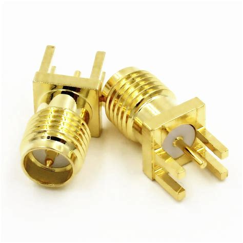
3. Board-to-Cable Connectors
Board-to-cable (B2C) connectors are used to connect a PCB to a cable assembly. They are designed to provide a reliable and secure connection between the board and the cable. Some common types of B2C connectors include:
3.1 D-Sub Connectors
D-Sub connectors, also known as D-subminiature connectors, are widely used in computer and communication equipment. They come in various sizes and pin counts, such as DB-9, DB-15, and DB-25, and are known for their durability and reliability.
3.2 Flat Flexible Cable (FFC) Connectors
FFC connectors are used to connect flat flexible cables to PCBs. These connectors are compact, lightweight, and offer high-density connections. They are commonly found in mobile devices, displays, and consumer electronics.
4. Power Connectors
Power connectors are designed to deliver electrical power to a PCB or other components. They come in various forms and ratings to accommodate different power requirements. Some common types of power connectors include:
4.1 Barrel Connectors
Barrel connectors, also known as coaxial power connectors, are cylindrical connectors with a central pin and an outer sleeve. They are commonly used in power supply applications, such as AC adapters and chargers.
4.2 Molex Connectors
Molex connectors are a family of connectors that are widely used for power and signal connections. They come in various sizes and configurations, such as the Mini-Fit and Micro-Fit series, and are known for their reliability and durability.

Factors to Consider When Choosing PCB Connectors
When selecting PCB connectors for your project, there are several factors to consider to ensure optimal performance and reliability:
-
Mechanical Specifications: Consider the physical dimensions, mounting type, and mating cycles of the connector to ensure compatibility with your PCB and enclosure.
-
Electrical Specifications: Evaluate the current rating, voltage rating, and contact resistance of the connector to ensure it meets your power and signal requirements.
-
Environmental Factors: Consider the operating temperature range, humidity, and vibration resistance of the connector based on the intended application environment.
-
Signal Integrity: For high-speed applications, consider connectors with shielding and impedance matching to minimize signal distortion and crosstalk.
-
Ease of Assembly: Choose connectors that are easy to assemble and maintain, considering factors such as Soldering Methods, cable management, and connector accessibility.

PCB Connector Selection Guide
To help you navigate the process of selecting the right PCB connector for your project, here’s a quick selection guide:
| Application | Recommended Connector Types |
|---|---|
| Board-to-Board (Parallel) | Mezzanine Connectors |
| Board-to-Board (Edge) | Edge Connectors |
| Wire-to-Board (Permanent) | Crimp Connectors |
| Wire-to-Board (Detachable) | Screw Terminal Connectors |
| Board-to-Cable (Data) | D-Sub Connectors, FFC Connectors |
| Power Delivery | Barrel Connectors, Molex Connectors |

Frequently Asked Questions (FAQ)
1. What is the difference between through-hole and surface-mount PCB connectors?
Through-hole PCB connectors have pins that are inserted into drilled holes on the PCB and soldered on the opposite side. Surface-mount connectors, on the other hand, are mounted directly onto the surface of the PCB using solder pads. Surface-mount connectors offer better space utilization and are suitable for automated assembly processes.
2. How do I determine the current rating of a PCB connector?
The current rating of a PCB connector is specified by the manufacturer and indicates the maximum amount of current that the connector can safely carry. It is important to choose a connector with a current rating that matches or exceeds the requirements of your application to prevent overheating and ensure reliable operation.
3. What is the purpose of shielding in PCB connectors?
Shielding in PCB connectors is used to reduce electromagnetic interference (EMI) and radio frequency interference (RFI). Shielded connectors have a metal shell or housing that surrounds the contacts, creating a barrier against external electromagnetic fields. This helps to maintain signal integrity and prevents interference from affecting the performance of the connected devices.
4. Can I mix and match different brands of PCB connectors?
While it is generally not recommended to mix and match different brands of PCB connectors, it is possible to do so if the connectors are compatible in terms of mechanical and electrical specifications. However, it is always best to use connectors from the same manufacturer and series to ensure optimal performance and reliability.
5. How do I ensure proper mating and unmating of PCB connectors?
To ensure proper mating and unmating of PCB connectors, follow these guidelines:
- Align the connectors carefully before mating to prevent damage to the pins or contacts.
- Apply gentle and even pressure when mating the connectors, avoiding excessive force.
- Use proper tools, such as extraction tools or ejector mechanisms, when unmating connectors to prevent damage.
- Regularly inspect the connectors for signs of wear, damage, or contamination, and replace them if necessary.
Conclusion
PCB connectors play a vital role in establishing reliable and efficient connections within electronic systems. Understanding the various types of PCB connectors and their specific applications is essential for designing and manufacturing robust and functional electronic devices. By considering factors such as mechanical and electrical specifications, environmental conditions, and signal integrity, you can select the most suitable connectors for your project.
As technology continues to advance, new types of PCB connectors are being developed to meet the evolving needs of the electronics industry. Keeping up with these advancements and staying informed about the latest connector solutions will help you stay ahead of the curve and create innovative and reliable electronic products.


Leave a Reply