Alumina 96% Al2O3 thermal conductivity is 24–28 W/mK at 25 °C, measured per ASTM E1461 (laser flash method). That is roughly 100× higher than FR-4 (0.25–0.3 W/mK) and adequate for most mid-power ceramic PCB applications, but well below aluminum nitride’s 170–200 W/mK. Whether 96% alumina meets your thermal budget depends on substrate thickness, heat flux density, and allowable junction-to-case temperature rise.
Key Takeaways
- Alumina 96% Al2O3 thermal conductivity sits at 24–28 W/mK at 25 °C; the exact value depends on grain size, porosity, and glassy-phase content.
- Thermal conductivity drops as temperature rises: expect roughly 15–18 W/mK at 300 °C.
- Upgrading to 99.6% alumina gains only a modest bump (28–35 W/mK); jumping to AlN (170–200 W/mK) is the move for high-flux designs.
- For a 0.635 mm substrate carrying 10 W over a 10 × 10 mm footprint, 96% alumina adds about 0.29 °C/W of conduction resistance—often a small fraction of total Rth.
- 96% alumina remains the lowest-cost ceramic substrate option, typically 30–50 % cheaper per unit area than AlN.
What Determines Alumina 96% Al2O3 Thermal Conductivity?
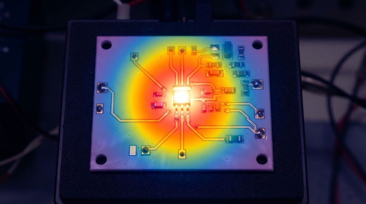
Alumina is a polycrystalline ceramic. Heat moves through it primarily by phonon conduction. Three microstructural variables control how easily phonons travel.
Purity and glassy phase. The “96%” label means the substrate is 96 wt% Al2O3 with 4 % glassy sintering aids (typically SiO2, MgO, CaO). That amorphous glass phase sits at grain boundaries and scatters phonons. More glass means lower conductivity. This is why 99.6% alumina, with far less glass, reaches 28–35 W/mK—a topic covered in detail on the 99.6% alumina thermal conductivity page.
Grain size. Larger grains mean fewer grain boundaries per unit length, reducing phonon scattering. Commercial 96% alumina substrates from suppliers like CoorsTek (ADS-96R) and Kyocera (A-473) have average grain sizes of 3–8 µm. Substrates sintered at higher temperatures for longer dwell times trend toward the upper end of the 24–28 W/mK range.
Porosity. Even small amounts of residual porosity (1–3 % is typical for 96% alumina) act as thermal voids. Each percentage point of porosity reduces effective conductivity by roughly 1–2 % according to the Maxwell-Eucken model.
How Temperature Changes Alumina 96% Al2O3 Thermal Conductivity
The thermal conductivity of 96% alumina is not a constant. It follows a roughly 1/T relationship above room temperature because phonon-phonon (Umklapp) scattering intensifies with rising temperature. The table below shows representative values from CoorsTek ADS-96R datasheets.
| Temperature (°C) | Thermal Conductivity (W/mK) | Source |
|---|---|---|
| 25 | 24–28 | CoorsTek ADS-96R datasheet; Kyocera A-473 datasheet |
| 100 | 21–25 | CoorsTek ADS-96R datasheet |
| 200 | 18–21 | CoorsTek ADS-96R datasheet |
| 300 | 15–18 | CoorsTek ADS-96R datasheet |
| 500 | 11–14 | Interpolated from CoorsTek published curves |
Typical values for commercially available material, for comparison only. Confirm against the datasheet for your specific grade.
If your device operates at elevated temperatures—power modules, downhole sensors, engine-adjacent electronics—use the conductivity at the actual operating temperature, not the 25 °C datasheet number. Plugging 26 W/mK into a simulation that runs at 200 °C will underestimate substrate thermal resistance by 25–35 %. For guidance on setting up accurate models, see thermal simulation for ceramic boards.
Enter your substrate material, thickness, and target temperature to see how alumina 96% Al2O3 thermal conductivity derates under your actual operating conditions.
Worked Example: Substrate Thermal Resistance
A designer needs to conduct 10 W through a 96% alumina substrate, 0.635 mm thick, under a 10 × 10 mm die at a steady-state junction temperature of 125 °C. Assume a substrate-surface temperature of roughly 85 °C, so the average substrate temperature is about 105 °C. At that temperature, use k ≈ 22 W/mK.
Conduction resistance through the substrate:
Rth,sub = t / (k × A) = 0.000635 m / (22 W/mK × 0.0001 m²) = 0.29 °C/W
Temperature drop across the substrate:
ΔT = Q × Rth,sub = 10 W × 0.29 °C/W = 2.9 °C
That 2.9 °C is manageable for many designs. But if the heat flux doubles to 20 W on the same footprint, the drop becomes 5.8 °C, and you start eating into your thermal margin. At that point, thinning the substrate to 0.38 mm or switching to AlN are both valid paths. A full walk-through of the math is on the thermal resistance calculation page.
96% Alumina vs. Other Ceramic Substrates
| Parameter | 96% Al2O3 | 99.6% Al2O3 | AlN | Si3N4 | Unit | Condition |
|---|---|---|---|---|---|---|
| Thermal conductivity | 24–28 | 28–35 | 170–200 | 60–90 | W/mK | 25 °C, ASTM E1461 |
| CTE | 7.1–7.4 | 7.0–7.2 | 4.5–4.8 | 2.5–3.2 | ppm/°C | 25–400 °C |
| Flexural strength | 340–380 | 350–400 | 300–350 | 600–900 | MPa | ASTM C1161 |
| Dielectric constant | 9.4–9.8 | 9.7–10.0 | 8.5–9.0 | 7.5–8.5 | — | 1 MHz |
| Relative cost (per cm²) | 1× | 1.3–1.8× | 3–5× | 4–6× | — | Volume pricing |
Typical values for commercially available material, for comparison only. Confirm against the datasheet for your specific grade.
96% alumina is the workhorse: affordable, widely available, and thermally adequate up to moderate power densities. When your thermal stack-up shows that the substrate accounts for less than 15–20 % of total Rth, paying 3–5× more for AlN delivers diminishing returns. For a broader comparison, the ceramic PCB thermal conductivity comparison table covers all common grades side by side.
If your design does demand higher substrate-level conductivity, aluminum nitride thermal conductivity is the next article to read.
When 96% Alumina Is Not Enough
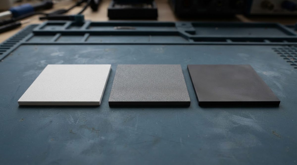
Choose a different substrate if any of these apply:
- Heat flux above ~25 W/cm² through the substrate. At this density, even a thin 96% alumina substrate contributes a significant ΔT. AlN or a direct-bonded copper (DBC) on AlN is the standard path for IGBT and SiC power modules.
- CTE match to silicon or SiC is critical. 96% alumina’s CTE of 7.1–7.4 ppm/°C is a reasonable match to copper lead frames but a poor match to bare silicon (2.6 ppm/°C). For large bare-die attach, AlN (4.5–4.8 ppm/°C) or Si3N4 (2.5–3.2 ppm/°C) reduce solder-joint fatigue.
- Cost must be minimal and thermal demands are low. If your board dissipates under 1–2 W total and doesn’t face harsh environments, FR-4 or metal-core PCB (MCPCB) will do the job at a fraction of the price.
- Mechanical shock and vibration are severe. Alumina is brittle. Si3N4 has roughly 2× the fracture toughness and is preferred for automotive power modules under thermal-cycling extremes.
Practical Design Tips for Maximizing Thermal Performance on 96% Alumina
Thin the substrate where possible. Going from 0.635 mm to 0.38 mm cuts conduction Rth by 40 %. The trade-off is reduced mechanical strength and tighter handling requirements. For thermal design rules specific to this material, see the alumina 96% thermal design guide.
Spread heat before it enters the ceramic. A copper plane or thick-film metallization on top of the substrate acts as a lateral heat spreader, reducing the effective flux density entering the alumina. Even 35 µm of copper spreads heat meaningfully over a 5 mm radius.
Use the correct k value in simulation. Map alumina 96% Al2O3 thermal conductivity as a temperature-dependent property, not a single number. Most FEA tools (ANSYS, COMSOL) accept tabular k(T) input. Using the 25 °C value throughout a 200 °C simulation introduces 25–35 % error in peak temperature prediction.
Account for interface resistances. Solder layers, thermal-interface materials, and even surface roughness at the die-substrate bond often dominate total Rth. A perfectly conductive substrate is irrelevant if the die-attach layer adds 0.5 °C/W.
Frequently Asked Questions
Is alumina 96% Al2O3 thermal conductivity the same across all suppliers?
No. Values range from 24 to 28 W/mK at 25 °C depending on the supplier’s sintering profile, grain size distribution, and glassy-phase chemistry. Always confirm with the specific datasheet—CoorsTek ADS-96R, Kyocera A-473, and Maruwa HA-96 each publish slightly different figures.
Does 96% alumina conduct heat better than aluminum metal?
No. Aluminum metal has a thermal conductivity of approximately 200–237 W/mK, roughly 8–10× higher than 96% alumina. Alumina’s advantage is electrical insulation, not raw thermal conductivity.
Can I improve 96% alumina’s thermal conductivity with thermal vias?
Thermal vias filled with copper or silver paste create parallel conduction paths through the substrate, lowering effective Rth. A dense via array under a heat source can reduce substrate thermal resistance by 30–60 %, depending on via diameter, pitch, and fill material. The details are covered in the thermal via design guide.
At what temperature does 96% alumina stop being usable?
The ceramic itself is stable above 1 000 °C, but the metallization, solder, and components on the PCB set practical limits. Thick-film gold or platinum conductors survive 500–850 °C; standard Sn-Ag-Cu solder remelts at 217–221 °C. The substrate’s thermal conductivity at 500 °C drops to roughly 11–14 W/mK, so thermal budgets tighten considerably at elevated temperatures.
How does 96% alumina compare to standard MCPCB for thermal management?
Metal-core PCBs use an aluminum base (150–200 W/mK) with a thin dielectric layer (1.5–5 W/mK, 75–150 µm thick). The dielectric layer is the bottleneck, giving total through-plane Rth comparable to or worse than a 0.38 mm alumina substrate. Alumina also offers higher operating temperature and better electrical isolation at high voltage.
Next Step
If your thermal stack-up shows that 96% alumina meets your conductivity needs, the next step is applying those numbers in a board-level design. The alumina 96% Al2O3 thermal design guide walks through layout rules, metallization choices, and via strategies specific to this substrate. When you are ready to get pricing on a specific design, request a quote through AluminaPCB.