Use a ceramic PCB when your board must survive continuous temperatures above 150 °C, dissipate more than about 5 W/cm² through the substrate, maintain tight impedance control above 10 GHz, or hold dimensional tolerances under ±25 µm across a production run. Knowing when to use ceramic PCB rather than an organic alternative comes down to seven measurable decision gates. Outside those envelopes, FR-4 or metal-core PCB is almost always cheaper and easier to source. The rest of this article gives you each gate with the numbers you need to make the call.
Key Takeaways
- Ceramic substrates (Al₂O₃ 96 %) conduct heat at 24–28 W/mK versus 0.25–0.35 W/mK for FR-4, per CoorsTek and Kyocera datasheets — roughly 80× better.
- Glass transition is irrelevant for ceramics; Al₂O₃ remains dimensionally stable to beyond 1 000 °C, while FR-4’s Tg sits at 130–180 °C.
- Ceramic PCBs typically cost 5–20× more per unit area than FR-4 at comparable layer counts, so the performance gap must justify the spend.
- The break-even point often comes from eliminating a heatsink, a thermal interface material, or a field-failure rate — not from the bare-board price alone.
- If your entire design runs below 130 °C, below 1 GHz, and below 2 W/cm², ceramic is almost certainly overkill.
Decision Gate 1: When to Use Ceramic PCB for Continuous Heat Above 150 °C
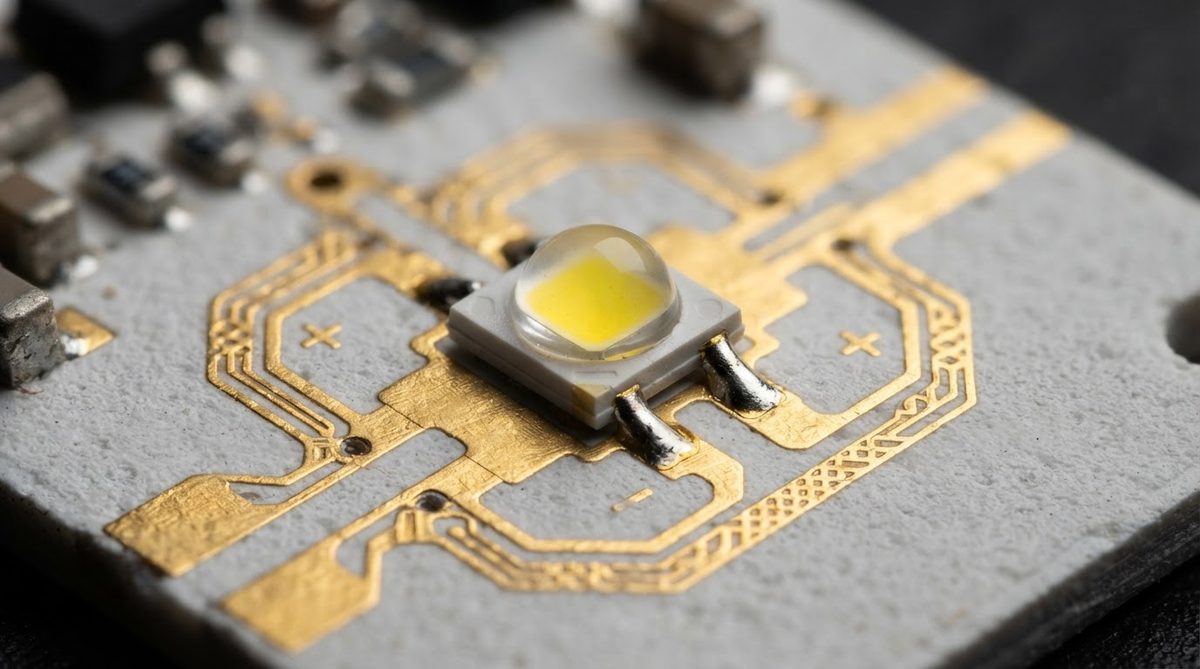
FR-4 is rated to a glass-transition temperature (Tg) of 130–180 °C depending on resin system, per IPC-4101. Above Tg, the laminate softens, delaminates, and outgasses. High-Tg polyimide pushes the limit to roughly 260 °C, but at a steep cost premium and with moisture-absorption trade-offs.
A 96 % alumina substrate has no organic component. It holds full mechanical strength past 800 °C. Aluminum nitride (AlN) is stable to similar temperatures. If your application — downhole oil-and-gas sensors, exhaust-gas monitoring, jet-engine instrumentation — needs the board itself to survive sustained heat above 150 °C, ceramic substrate materials are the shortest path to a reliable design. For environments at the opposite extreme, ceramic substrates at cryogenic temperatures also outperform organics because they do not become brittle or crack from CTE mismatch the way epoxy laminates can.
Enter your expected operating temperature and substrate thickness to see how ceramic derating compares with FR-4 across the full temperature range.
Decision Gate 2: Thermal Flux Density Above ~5 W/cm²
Power LEDs, GaN HEMTs, SiC MOSFETs, and bare-die laser diodes all concentrate heat in a small footprint. When the local flux exceeds roughly 5 W/cm², the thermal resistance of FR-4 (even with heavy copper and thermal vias) creates a junction-temperature bottleneck. This is one of the clearest scenarios for when to use ceramic PCB over organic alternatives.
Worked Example: 10 W LED on Al₂O₃ vs. FR-4
Assume a 3 × 3 mm thermal pad, substrate thickness 0.635 mm, one-dimensional conduction.
| Parameter | FR-4 | Al₂O₃ 96 % | AlN |
|---|---|---|---|
| k (W/mK) | 0.30 | 26 | 180 |
| Area (m²) | 9 × 10⁻⁶ | 9 × 10⁻⁶ | 9 × 10⁻⁶ |
| Thickness (m) | 6.35 × 10⁻⁴ | 6.35 × 10⁻⁴ | 6.35 × 10⁻⁴ |
| Rth = t / (k × A) (°C/W) | 235 | 2.7 | 0.39 |
| ΔT at 10 W (°C) | 2 352 | 27 | 3.9 |
Typical values for commercially available material, for comparison only. Confirm against the datasheet for your specific grade.
The FR-4 number is physically meaningless — the board would char long before reaching a 2 352 °C rise. Even with a dense via array cutting effective Rth by 60–70 %, FR-4 still leaves you at hundreds of degrees. Alumina drops the substrate contribution to 27 °C; AlN makes it nearly negligible. If your thermal budget is tight, ceramic earns its price here. For UV-C LED designs that push flux density even further, AlN substrates for UV LEDs are a common solution.
Decision Gate 3: RF and Millimeter-Wave Performance Above 10 GHz
FR-4 has a dissipation factor (Df) of 0.018–0.025 at 1 GHz (per IPC-TM-650 2.5.5.9). At 24 GHz or 77 GHz — automotive radar, 5G mmWave — that loss makes it unusable. Rogers RO4350B (Df ≈ 0.0037) fills the gap for many RF boards, but when you also need hermeticity, high thermal conductivity, or very tight dimensional stability, 96 % or 99.6 % alumina (Df 0.0001–0.0003 at 1 MHz, per Kyocera A-493 datasheet) is the better substrate.
The low and stable dielectric constant of alumina (9.6–9.8 at 1 MHz) does mean wider traces for 50 Ω lines compared to PTFE laminates, so plan your layout accordingly. For designs requiring controlled-impedance multilayer routing at these frequencies, multilayer ceramic PCB builds using LTCC or HTCC can integrate stripline structures directly.
Decision Gate 4: Dimensional and Positional Tolerance
Organic laminates expand, contract, and absorb moisture. A standard FR-4 panel can shift ±75 µm or more across a 100 mm span during lamination. Ceramic substrates, fired at 1 400–1 600 °C, are dimensionally locked. Position tolerances of ±10–25 µm are routine on laser-patterned alumina. This matters for flip-chip bonding, wire bonding, and optical alignment where pad-to-pad accuracy drives yield.
Decision Gate 5: Hermeticity and Outgassing
Vacuum and space environments demand substrates that neither outgas nor absorb moisture. FR-4 fails both tests. Ceramics are fully inorganic, non-hygroscopic, and can be brazed into hermetic packages. If your board lives inside a sealed sensor, a satellite, or a medical implant, ceramic is often a design requirement rather than a preference.
Decision Gate 6: Chemical and Radiation Resistance
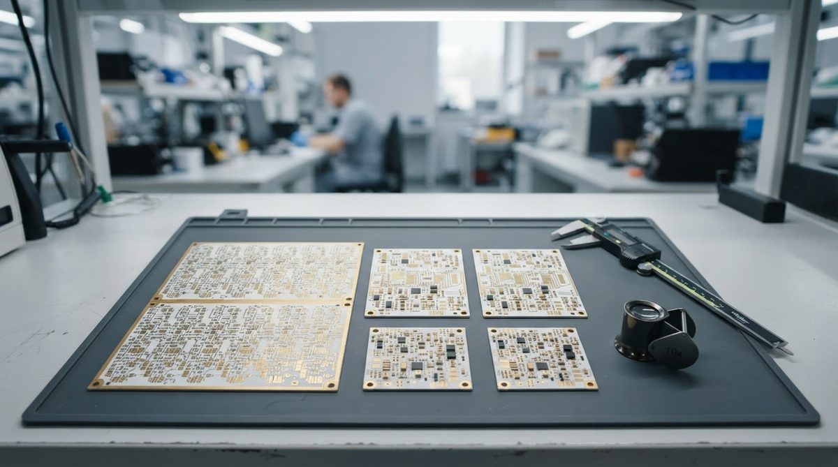
Alumina and AlN resist most acids, bases, and organic solvents. They also tolerate ionizing radiation far better than epoxy-glass, which degrades at cumulative doses above roughly 10–100 krad (Si) depending on resin. Nuclear instrumentation, particle-physics detectors, and some space missions specify ceramic substrates for this reason. Understanding when to use ceramic PCB in these harsh environments can prevent costly field failures.
Decision Gate 7: System-Level Cost Reduction
This is the gate most engineers skip. A ceramic PCB is more expensive per board, but the total system cost can drop if the ceramic eliminates one or more of the following:
- A separate heatsink and thermal interface material (TIM).
- A conformal coating or potting step for chemical protection.
- A hermetic package or housing.
- Field failures and warranty costs from thermal cycling fatigue.
Run the comparison at the assembly level, not the bare-board level. If the ceramic board costs $12 but removes a $6 heatsink, a $2 TIM pad, and $3 of assembly labor, the net premium is $1 — and you gain reliability margin on top.
When NOT to Use a Ceramic PCB
Ceramic is the wrong choice in several common situations:
- Consumer electronics at scale. If you need 100 k+ units of a board that runs below 100 °C and below 1 GHz, FR-4 wins on cost, lead time, and supply-chain depth.
- Large board area. Ceramic substrates are typically limited to panels under 150 × 150 mm. If your design is 200 × 300 mm, you are looking at tiling or a different substrate entirely.
- High layer count with complex routing. LTCC and HTCC can build multilayer structures, but 12+ layer ceramic boards are rare, expensive, and slow to iterate. A 16-layer FR-4 or Rogers hybrid stackup is far more practical for dense digital routing.
- Mechanical shock and vibration without proper mounting. Ceramics are brittle. A 1.5 mm thick alumina board dropped on concrete will shatter. If your product faces repeated mechanical shock (handheld tools, field equipment), design the mounting carefully or choose a tougher substrate like Si₃N₄ — or stick with FR-4.
- Prototype iteration speed. FR-4 prototype turns of 24–48 hours are common. Ceramic prototypes typically take 1–3 weeks. If you are in early schematic exploration and expect many board spins, start on FR-4 and move to ceramic once the design is frozen.
Quick Decision Matrix
| Your Requirement | FR-4 / MCPCB Handles It? | Ceramic Needed? |
|---|---|---|
| Top < 130 °C, flux < 2 W/cm² | Yes | No |
| Top 130–200 °C, moderate flux | Maybe (polyimide, MCPCB) | Evaluate |
| Top > 200 °C | No | Yes |
| Flux > 5 W/cm², tight thermal budget | No | Yes |
| RF > 10 GHz with thermal or hermetic need | No | Yes |
| Positional tolerance < ±25 µm | No | Yes |
| Vacuum / hermetic / zero outgassing | No | Yes |
| Board area > 150 × 150 mm, high layer count | Yes | Rarely practical |
FAQ
How much more does a ceramic PCB cost than FR-4?
Expect 5–20× the bare-board cost per unit area for a single- or double-sided ceramic board versus standard FR-4 at similar quantities. The gap narrows at small board sizes (under 25 × 25 mm) and widens for larger panels. Always compare at the assembly level, including heatsinks and TIMs you may be able to eliminate.
Can I solder standard SMD components to a ceramic PCB?
Yes. Standard SAC305 or SnPb solder and conventional reflow profiles work on metallized ceramic substrates. The main difference is that ceramics have a lower CTE (6–7 ppm/°C for alumina) versus FR-4 (14–17 ppm/°C), so large BGA packages may need CTE-management strategies such as underfill. See the reflow profile guide for ceramic PCBs for profile specifics.
Is ceramic PCB suitable for flexible or flex-rigid designs?
No. Ceramic substrates are rigid and brittle. They cannot bend. If your design requires flex sections, use polyimide flex or a rigid-flex stackup and reserve ceramic only for a localized high-performance sub-assembly that connects to the flex circuit via a connector or solder joint.
What is the minimum practical order for ceramic PCBs?
Most ceramic PCB fabricators accept orders starting at 1–5 pieces for prototypes. Production MOQs vary but often start at 50–100 pieces per design. Lead times for prototypes are typically 1–3 weeks, longer than FR-4 quick-turns. Ceramic PCB fabrication capabilities vary by manufacturer, so confirm with your supplier early.
Does ceramic PCB need a special surface finish?
Ceramic boards accept most standard finishes: ENIG, ENEPIG, OSP, bare copper, and gold plating. The choice depends on your soldering method, wire-bonding requirements, and operating environment — the same factors that drive finish selection on any board. The ceramic PCB glossary defines each finish abbreviation if needed.
Next Step
If two or more of the seven decision gates above apply to your project, a ceramic PCB is likely worth a serious look. Start by selecting the right substrate material — alumina, AlN, or Si₃N₄ — based on your thermal and mechanical requirements. Then request a quote with your Gerber files or a dimensioned sketch to get real pricing for your specific board size and quantity.