Introduction to Circuit Jumper Wires
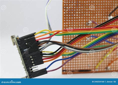
Circuit jumper wires, also known as jumper cables or jumpers, are short electrical wires used to create temporary connections between points on a circuit board or breadboard. Jumper wires allow you to modify, test, and prototype electronic circuits without the need for soldering. They are an essential tool for electronics hobbyists, students, and professionals alike.
Types of Circuit Jumper Wires
There are several types of jumper wires available, each with its own characteristics and applications:
| Type | Description |
|---|---|
| Male-to-Male (M-M) | Both ends have male connectors (pins) |
| Male-to-Female (M-F) | One end has a male connector, the other a female connector |
| Female-to-Female (F-F) | Both ends have female connectors (sockets) |
| Solid Core | Made from a single strand of solid wire |
| Stranded | Made from multiple strands of thin wire twisted together |
M-M jumpers are used to connect two male headers or pins, while M-F jumpers connect a male header to a female header. F-F jumpers join two female headers together. Solid core jumpers are more rigid and maintain their shape, while stranded jumpers are more flexible.
Preparing to Bond Jumper Wires
Before bonding jumper wires to a circuit board, there are several steps you should take to ensure a successful and reliable connection.
Tools and Materials Needed
- Circuit board or breadboard
- Jumper wires
- Wire strippers
- Soldering iron and solder
- Flux (optional)
- Helping hands or PCB holder (optional)
Stripping Jumper Wire Ends
- Determine the length of wire needed for your connection.
- Use wire strippers to remove approximately 1/4 inch (6mm) of insulation from each end of the jumper wire.
- Twist the exposed strands together to form a neat, compact bundle.
Tinning Jumper Wire Ends
Tinning the stripped ends of the jumper wire helps to prevent fraying and makes soldering easier.
- Heat your soldering iron to the appropriate temperature (typically 600-700°F or 315-370°C).
- Apply a small amount of solder to the tip of the iron.
- Touch the solder-coated tip to the exposed wire strands, allowing the solder to wick into the wire.
- Remove the iron and let the solder cool and solidify.

Bonding Jumper Wires to Circuit Boards
Through-Hole Soldering
- Insert the tinned end of the jumper wire into the desired hole on the circuit board.
- Place the tip of the soldering iron against both the wire and the pad surrounding the hole.
- Apply solder to the joint, allowing it to melt and flow around the wire and pad.
- Remove the soldering iron and let the joint cool.
Surface Mount Soldering
- Apply a small amount of solder to the pad where the jumper wire will be attached.
- Place the tinned end of the jumper wire onto the solder-coated pad.
- Touch the soldering iron to the wire and pad, causing the solder to melt and bond the wire to the pad.
- Remove the iron and allow the joint to cool.
Reinforcing and Protecting Solder Joints
To improve the strength and durability of your solder joints, you can:
- Apply a small amount of flux to the joint before soldering to help the solder flow more easily and create a stronger bond.
- Use heat shrink tubing or insulating tape to cover the joint, protecting it from mechanical stress and short circuits.

Testing and Troubleshooting
After bonding your jumper wires, it’s crucial to test your connections to ensure they are functioning correctly.
Continuity Testing
Use a multimeter to perform a continuity test:
- Set the multimeter to the continuity or resistance setting.
- Touch one probe to one end of the jumper wire and the other probe to the corresponding point on the circuit board.
- If the multimeter beeps or shows a low resistance value, the connection is good. If not, the joint may be faulty.
Visual Inspection
Visually inspect your solder joints for:
- Cold joints: Dull, bumpy, or cracked appearance, indicating poor bonding.
- Insufficient solder: The joint appears concave or doesn’t fully cover the wire and pad.
- Excess solder: Large, bulbous joints that may cause short circuits.
If you find any issues, reheat the joint with your soldering iron and add or remove solder as needed.

Best Practices for Circuit Jumper Wires
To ensure optimal performance and longevity of your jumper wire connections, follow these best practices:
- Use the appropriate wire gauge for your project, typically 22-28 AWG for most applications.
- Keep jumper wires as short as possible to minimize resistance and signal degradation.
- Route jumper wires neatly and avoid crossing them whenever possible to reduce electromagnetic interference.
- Use color-coded jumper wires to help identify connections and make your project more organized.
- Replace damaged or frayed jumper wires promptly to prevent short circuits or signal loss.
Advanced Techniques
Daisy-Chaining Jumper Wires
Daisy-chaining involves connecting multiple points using a single jumper wire, which can save space and reduce the number of wires needed.
- Strip a longer section of insulation from the jumper wire, exposing enough wire to reach all the desired points.
- Tin the entire exposed portion of the wire.
- Solder the wire to the first point, then lay it across the other points, soldering it at each location.
Creating Custom Jumper Wires
If you need jumper wires of specific lengths or colors, you can create your own:
- Cut the desired length of wire from a spool of insulated wire.
- Strip both ends of the wire and tin them as described earlier.
- Attach male or female connectors to the ends using crimp tools or solder.
Frequently Asked Questions (FAQ)
1. Can I use jumper wires without soldering?
Yes, you can use jumper wires with breadboards or other prototyping boards that have sockets for inserting the wire ends directly. However, for permanent connections on circuit boards, soldering is recommended for better reliability and durability.
2. How do I choose the right gauge jumper wire for my project?
The choice of wire gauge depends on the current carrying capacity needed and the space constraints of your project. Generally, 22-28 AWG wires are suitable for most low-current applications. Refer to a wire gauge chart to determine the appropriate size for your specific requirements.
3. Can I solder jumper wires directly to components?
Yes, you can solder jumper wires directly to component leads, such as resistors, capacitors, or IC pins. However, be cautious not to overheat the component, as excessive heat can damage it. Use a heat sink or work quickly to minimize heat transfer.
4. How do I remove a soldered jumper wire?
To remove a soldered jumper wire, first heat the solder joint with your soldering iron. Then, gently pull the wire away from the joint using tweezers or pliers. If the wire is stubborn, you may need to add a small amount of fresh solder to the joint to help melt the old solder and release the wire.
5. Can I use jumper wires for high-frequency or RF applications?
For high-frequency or RF applications, jumper wires may introduce unwanted inductance and signal interference. In these cases, it’s better to use specialized wires, such as coaxial cables or twisted pairs, which are designed to minimize signal distortion and crosstalk. Additionally, proper shielding and grounding techniques should be employed to ensure signal integrity.
Conclusion
Bonding circuit board jumper wires is a fundamental skill for anyone working with electronics. By following the techniques and best practices outlined in this article, you can create reliable, efficient, and professional-looking connections for your projects. Remember to choose the appropriate tools and materials, work carefully and methodically, and always test your connections to ensure optimal performance. With practice and patience, you’ll be able to confidently tackle any project that requires circuit jumper wires.


Leave a Reply