A ceramic PCB prototype line optimizes for speed and flexibility; a production line optimizes for unit cost and repeatability. Understanding the ceramic PCB prototype vs production distinction matters because choosing the wrong line wastes either money or time. Prototypes on a production line mean paying for tooling you may scrap after a design revision. Production volumes on a prototype line mean inflated per-unit costs and inconsistent yield screening. The decision hinges on quantity, design maturity, and how much process qualification your end application demands.
Key Takeaways
- Prototype runs typically cover 1–50 pieces with shared tooling and ship in 5–10 business days; production runs start at 100+ pieces with dedicated tooling and ship in 15–25 business days.
- Unit cost on a prototype line can be 3–8× higher than production pricing because setup costs are amortized over fewer boards.
- Production lines add incoming inspection, SPC monitoring, and lot traceability that prototype lines often skip.
- Switching from prototype to production usually requires a first-article inspection (FAI) and may require re-qualifying the metallization process.
- Design changes after production tooling is cut cost 2–5× more than changes during the prototype phase.
What Differs Between Ceramic PCB Prototype vs Production Lines
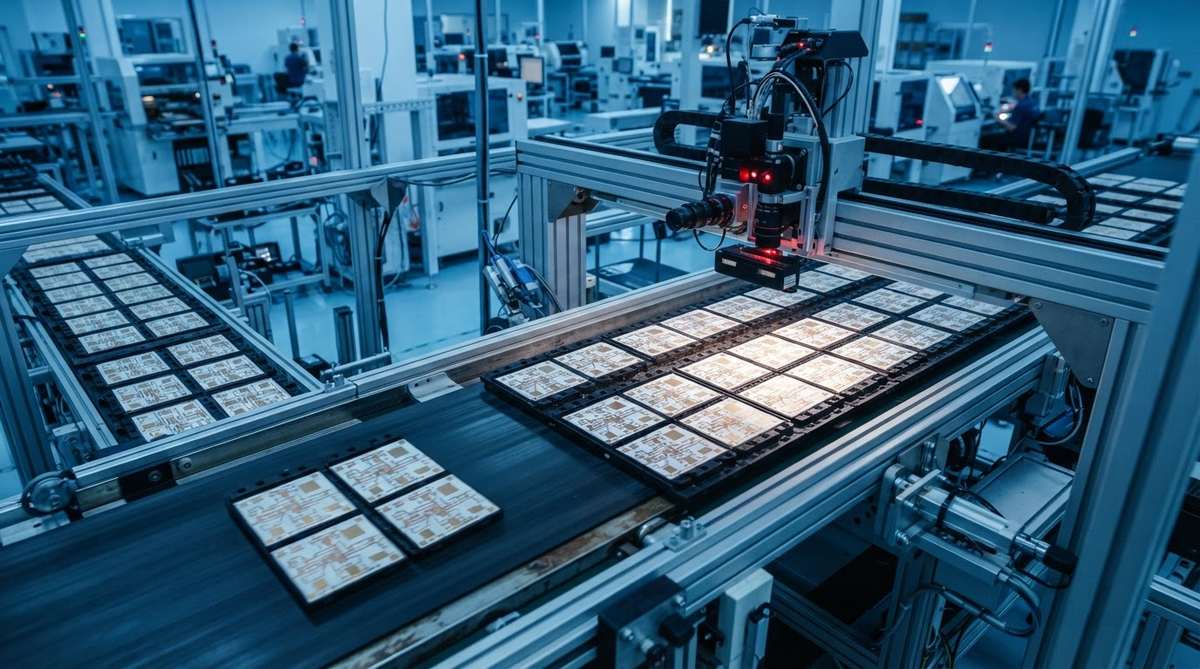
The substrate material is the same. A 96% alumina blank fired for a prototype is chemically identical to one fired for production. The differences are in how the factory handles tooling, scheduling, inspection, and documentation around that blank.
On a prototype line, the factory uses generic fixtures, shared laser programs, and minimal custom tooling. Operators may hand-load panels and visually inspect each board. This keeps non-recurring engineering (NRE) charges low and turnaround fast. On a production line, the factory builds dedicated screen-print stencils or photomasks, custom break-away fixtures, and automated panel handling. Inspection shifts from operator judgment to AOI and SPC-controlled sampling plans per IPC-6012 Class 2 or Class 3 requirements.
Tooling and Setup
Prototype tooling is often “soft”—laser-cut stencils, shared alignment jigs, and general-purpose fixtures. Production tooling is “hard”—photo-etched stencils for thick-film printing, dedicated DBC or DPC process fixtures, and custom test jigs. Hard tooling costs more upfront but produces tighter registration and higher throughput. For a typical 25 × 25 mm DPC circuit, expect NRE of $200–$500 for prototype tooling versus $800–$2,000 for production tooling, depending on layer count and feature complexity.
Quality and Documentation
Prototype boards usually ship with a basic dimensional check and visual inspection report. Production boards ship with full lot traceability, material certificates, cross-section data (if specified), and statistical process control records. If your end product needs IPC Class 3 acceptance or automotive-grade documentation, those requirements must be specified before the production line is set up—not retrofitted after the fact. This quality gap is one of the most consequential aspects of the ceramic PCB prototype vs production decision.
Cost Breakdown: Prototype vs Production
The table below shows a representative cost comparison for a single-layer DPC circuit on 96% Al₂O₃, 25 × 25 mm, with ENIG finish. These are illustrative ranges, not quotes.
| Cost Element | Prototype (10 pcs) | Production (500 pcs) | Notes |
|---|---|---|---|
| NRE / tooling | $300 | $1,200 | Production uses dedicated photo-mask and stencil |
| Substrate blanks | $5.00 / pc | $2.50 / pc | Volume pricing on bulk blanks |
| Metallization | $12.00 / pc | $4.00 / pc | Batch efficiency on production line |
| Surface finish (ENIG) | $3.00 / pc | $1.20 / pc | Shared bath chemistry in both cases |
| Inspection & test | $2.00 / pc (visual) | $1.50 / pc (AOI + hipot) | Production adds SPC overhead but spreads it |
| Total per piece | $52.00 | $11.60 | Includes NRE amortized across qty |
Illustrative figures for comparison only. Actual pricing depends on material grade, metallization process, and specifications. Request a project-specific quote for accurate numbers.
For a deeper look at what drives these numbers, see our ceramic PCB cost breakdown.
Worked Example: When Does Production Pricing Break Even?
Assume prototype NRE is $300 and per-piece cost is $22.00. Production NRE is $1,200 and per-piece cost is $9.20. Setting total cost equal:
300 + 22.00 × N = 1,200 + 9.20 × N
12.80 × N = 900
N ≈ 70 pieces
Below 70 pieces, the prototype line is cheaper overall. Above 70, production wins. This crossover point shifts with board complexity. A multilayer HTCC or LTCC design with tighter tolerances pushes the crossover higher because production tooling costs more. A simple single-layer thick-film board pushes it lower.
Enter your own NRE, per-piece costs, and target quantity to find the crossover point for your specific ceramic PCB prototype vs production decision.
When to Stay on the Prototype Line
Stay on the prototype line when any of these are true:
- Your design is not frozen. If you expect another revision, spending on production tooling is premature.
- You need fewer than ~50–100 pieces total, including all revisions.
- You are evaluating multiple material options—say, comparing alumina 96% against FR-4 or AlN—and need small batches of each for thermal testing.
- Your schedule cannot absorb the 2–4 week tooling lead time that production requires on top of the build time.
Prototype lines also make sense for one-off test vehicles, coupon builds for material qualification, and failure-analysis replacements where you need five boards by next week.
When to Move to the Production Line
Move to production when your design is locked, your quantity exceeds the break-even point, and your application demands repeatable process controls. Specifically:
- You have passed design verification testing (DVT) and the layout is frozen.
- Your customer or end-use standard requires lot traceability, CPK data, or first-article inspection per AS9102 or PPAP.
- You need 100+ pieces per release, or cumulative annual volume exceeds 500 pieces.
- Yield matters. Production lines with dedicated tooling and SPC typically hit 95–98% yield on mature designs versus 85–92% on prototype lines running the same geometry.
The Transition: Prototype to Production Qualification
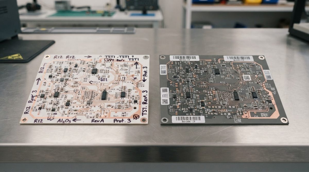
Switching lines is not just placing a bigger order. A responsible fabricator will run a first-article inspection (FAI) on the production line, comparing critical dimensions, adhesion pull-test results, and electrical isolation against your prototype-validated specification. For DBC versus AMB metallization, the bonding process parameters may differ between prototype and production furnaces, so re-qualification is not optional—it is a real engineering step.
What to Provide When Transitioning
- Frozen Gerber or ODB++ data. No “preliminary” files. The production line will build hard tooling from these.
- A complete fabrication drawing with all dimensions, tolerances, material callouts, and acceptance criteria.
- Prototype test data. Share your DVT results so the fabricator knows which parameters are critical.
- Annual volume forecast. This determines whether the factory sets up a dedicated line or schedules batch runs.
Common Mistakes in Ceramic PCB Prototype vs Production Decisions
Ordering production tooling before the design is stable. Every revision means re-cutting stencils and masks. Two revisions can cost more in scrapped tooling than the entire prototype phase would have.
Assuming prototype quality equals production quality. A prototype board that passes your bench test may not represent the process window of a production run. Prototype operators often cherry-pick the best boards. Production yield includes every board off the line.
Skipping FAI. If your prototype was built on a different line with different fixtures, the production boards may have subtle dimensional shifts. A 50 µm registration error that was absent on the prototype line can appear on the production line if the tooling was built from slightly different alignment references.
When Neither Line Is the Right Choice
If your thermal requirements can be met by a metal-core PCB (MCPCB) or standard FR-4 with thermal vias, ceramic may not justify its cost at any volume. An MCPCB versus ceramic thermal comparison often shows that MCPCB wins below 2 W/cm² heat flux density for single-sided designs. Similarly, if your prototype run is purely for mechanical fit-check with no electrical function, a CNC-machined alumina blank without metallization may be faster and cheaper than either PCB line.
For RF applications where impedance control is critical, confirm that the prototype line can hold the same dielectric tolerance as the production line. If it cannot, your prototype test results will not transfer, and you may need to prototype on the production line from the start—accepting the higher NRE and longer lead time.
Frequently Asked Questions
Can I use prototype boards in a final product?
Yes, if they meet your acceptance criteria. Prototype boards are made from the same materials and processes. The risk is that they lack the lot traceability and SPC documentation that regulated industries require. For medical, automotive, or aerospace end use, most quality systems will not accept boards without full production documentation.
How many prototype revisions should I budget for?
Two to three revisions is typical for a new ceramic PCB design. Budget time and cost for at least two spins. If your design involves a new-to-you process like thick film versus thin film metallization, add one more revision for process learning.
Does the prototype line use the same substrate material as production?
Yes. The alumina, AlN, or Si₃N₄ substrate is identical. Differences arise in tooling, fixturing, and inspection rigor—not in the ceramic itself.
Will my prototype pricing predict my production unit cost?
No. Prototype unit cost includes amortized NRE over a small batch and lacks the throughput efficiencies of a production line. Expect production unit cost to be 50–80% lower than prototype unit cost for the same design, depending on volume.
Can I split an order—some boards from prototype, some from production?
Technically yes, but it is rarely advisable. Boards from different lines may have measurable differences in copper thickness, registration, or surface finish thickness. If you need mixed quantities, discuss this with your fabricator so they can align process parameters or flag where differences will appear.
Next Step
If your design is still evolving, start with a prototype order and plan for a production qualification run once the layout is frozen. If you already have frozen files and need volume pricing, send your Gerbers for a quote along with your fabrication drawing and target quantity. Specifying your design maturity upfront saves time on both sides.