Laser scribing ceramic is a controlled-depth grooving process that scores ceramic panels along predefined break-out lines so individual substrates snap apart cleanly after all metallization and assembly steps are complete. The groove typically penetrates 30–50 % of the substrate thickness, leaving enough material for handling strength during processing while ensuring a predictable fracture path during singulation. Compared to full-through laser cutting, laser scribing ceramic substrates is faster, generates less heat-affected zone (HAZ), and preserves tighter dimensional tolerances on the finished part.
Key Takeaways
- Scribe grooves are usually 30–50 % of substrate thickness and 20–80 µm wide, depending on laser type and ceramic grade.
- CO₂ lasers (10.6 µm wavelength) are the most common choice for Al₂O₃ scribing; UV and green Nd:YAG/Nd:YVO₄ lasers suit AlN and thinner substrates.
- Positional accuracy of the scribe line is typically ±0.025–0.05 mm, tighter than mechanical scribing (±0.10 mm).
- Scribe-and-break leaves a rougher edge (Ra 3–8 µm) than full laser cutting (Ra 1–3 µm), which matters only if the edge is a sealing or bonding surface.
- Design rules require a keep-out zone of at least 0.3 mm between the scribe line and the nearest conductor or via.
How Laser Scribing Ceramic Differs from Laser Cutting
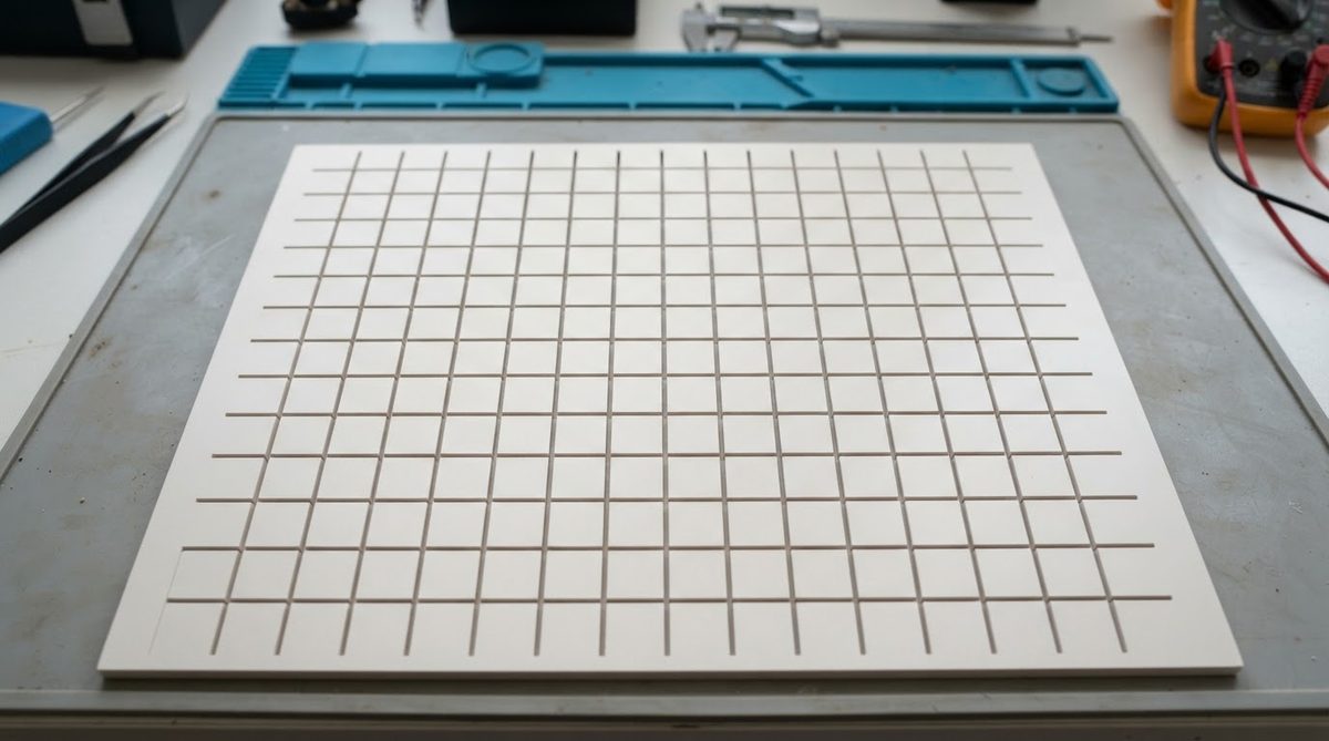
Both processes use a focused laser beam on a ceramic panel, but they serve different purposes. Laser cutting slices completely through the substrate in a single pass or multiple passes, producing a finished edge. Laser scribing removes material only partway through, creating a V- or U-shaped groove that acts as a stress concentrator. The panel is then broken along the groove mechanically—by hand, with a fixture, or with a roller breaker.
Scribing is preferred when panels carry many small units that benefit from batch processing through ceramic metallization, soldering, and testing while still attached. Full cutting is chosen when edge quality must be pristine, when geometries are non-rectangular, or when the substrate is too thick for reliable break-out. For a detailed look at full-cut parameters and tolerances, see the laser cutting capabilities and tolerances page.
| Parameter | Laser Scribing | Full Laser Cutting | Mechanical Scribing |
|---|---|---|---|
| Cut depth | 30–50 % of thickness | 100 % | 20–40 % of thickness |
| Kerf width | 20–80 µm | 50–150 µm | 80–200 µm |
| Positional accuracy | ±0.025–0.05 mm | ±0.025–0.05 mm | ±0.10 mm |
| Edge roughness (Ra) | 3–8 µm | 1–3 µm | 5–15 µm |
| Micro-crack risk | Low | Very low | Moderate |
| Speed (relative) | Fast | Slow (multiple passes) | Fast |
| Non-rectangular shapes | No (straight lines only) | Yes | No |
Typical values for commercially available equipment and 96 % Al₂O₃ at 0.381 mm thickness, for comparison only. Confirm against your specific grade and equipment setup.
Laser Types Used for Scribing Ceramic Substrates
The choice of laser depends on the ceramic material and the required groove geometry.
CO₂ Lasers (10.6 µm)
Al₂O₃ absorbs strongly at 10.6 µm, making CO₂ lasers the workhorse for alumina scribing. Power levels of 25–100 W handle substrates from 0.25 mm to 1.0 mm thick. The relatively large spot size (100–200 µm focused) produces a wider groove but scribes quickly—linear speeds of 100–500 mm/s are typical. Heat input is moderate; the HAZ extends roughly 20–50 µm from the groove wall in 96 % Al₂O₃, per published data from Rofin/Coherent application notes.
UV and Green Solid-State Lasers (355 nm / 532 nm)
Shorter wavelengths produce a smaller spot (10–30 µm) and a narrower groove (20–40 µm). They are preferred for AlN, which absorbs UV better than mid-IR, and for thin substrates (≤0.25 mm) where a tight HAZ is critical. Processing speed is slower—50–200 mm/s—and equipment cost is higher. These lasers also suit panels that have already been through ceramic firing and sintering, where minimizing thermal shock to the finished surface is important.
Ultrashort-Pulse (Picosecond / Femtosecond) Lasers
These remove material by cold ablation, virtually eliminating HAZ. They are used in research and very high-value production (e.g., MEMS sensor substrates) but are rarely cost-justified for standard panel break-out. Scribing speeds are 10–50 mm/s, and capital cost is 3–5× that of a CO₂ system.
Process Steps: From Panel to Individual Substrates
- Panel preparation. The fired, bare ceramic panel is cleaned and fiducials are aligned on the laser stage. Panels are typically scribed before metallization in LTCC workflows, but after metallization in DPC and thick-film workflows. The choice depends on whether the scribe groove would interfere with subsequent deposition steps.
- Laser parameter setup. Power, pulse rate, scan speed, and number of passes are set based on material, thickness, and target groove depth. A test scribe on a sacrificial coupon confirms groove depth under a microscope before production begins.
- Scribing. The laser traces each break-out line. Orthogonal X and Y lines are scribed sequentially. Intersection points receive a double dose of energy, so dwell time is often reduced at crossings to prevent over-ablation.
- Post-scribe processing. The panel proceeds through remaining manufacturing steps—metallization, via filling, component attach, or testing—while still intact.
- Break-out. A roller breaker or manual fixture applies bending stress along the scribe line. The substrate fractures along the groove. Edges are inspected for chips or deviation.
Enter your substrate material, thickness, and target groove percentage below to see estimated laser parameters and derating factors for your specific panel.
Design Rules for Laser Scribing Ceramic Panels
Poor scribe-line placement is the most common cause of cracked substrates and conductor damage during break-out. Follow these rules when laying out a panelized ceramic design.
- Keep-out zone: Maintain at least 0.3 mm between the scribe line centerline and the nearest copper trace, pad, or via. For thick-film conductors, increase this to 0.5 mm because paste can wick into the groove during printing. Refer to thick-film ceramic design rules for additional clearance guidance.
- Groove depth target: 35–45 % of substrate thickness gives the best balance between handling strength and clean fracture. Below 30 %, the fracture path wanders and edge chips increase. Above 50 %, panels may crack prematurely during handling.
- Line straightness: Scribe lines must be straight and continuous. L-shaped or curved break-out is not possible with scribe-and-break; use full laser cutting for those geometries.
- Panel border: Leave a minimum 1.0 mm border between the outermost scribe line and the panel edge. This prevents chipping during roller break-out.
- Intersection relief: At X–Y crossings, reduce laser power or speed to compensate for the double-groove overlap. Some CAM systems handle this automatically.
Worked Example: Groove Depth for 0.635 mm Al₂O₃ 96 %
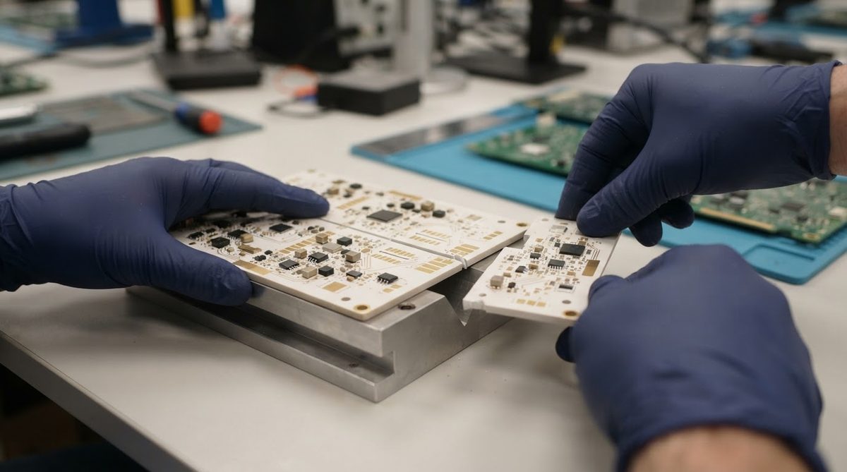
Suppose you have a 0.635 mm (25 mil) thick alumina panel and want a target groove depth of 40 %. This is a common scenario when laser scribing ceramic substrates for high-volume LED or sensor arrays.
Target groove depth = 0.635 mm × 0.40 = 0.254 mm.
Using a CO₂ laser at 50 W average power, 10 kHz pulse rate, and 200 mm/s scan speed, a single pass on 96 % Al₂O₃ typically removes roughly 80–120 µm of material (per Coherent/Rofin application data for standard alumina). Two passes at these settings yield approximately 160–240 µm. A third pass would overshoot the 254 µm target, so the approach is: two passes at 200 mm/s, then a single pass at 300 mm/s (reduced energy per unit length) to reach the remaining 14–94 µm. The exact recipe is confirmed by cross-sectioning a test coupon and measuring groove depth with a calibrated optical microscope.
This iterative calibration step is not optional. Groove depth varies with ceramic porosity, surface finish, and even batch-to-batch differences in the substrate. Always verify on a coupon from the same production lot.
When Not to Use Laser Scribing
Laser scribing ceramic panels is not the right choice in every situation.
- Non-rectangular outlines. Scribe-and-break only works for straight lines. If your design requires rounded corners, notches, or irregular shapes, use full laser cutting or CNC routing.
- Very thick substrates (>1.0 mm). Break-out force increases with thickness, and the fracture path becomes less predictable. Full-through cutting or diamond sawing is safer above 1.0 mm.
- Edge-critical assemblies. If the substrate edge is a sealing surface, a hermetic joint, or a precision-fit interface, the 3–8 µm Ra of a scribe-and-break edge may be too rough. Lapping and polishing after break-out can improve this, but it adds cost and handling.
- Single-unit production. Scribing is a panelization technique. If you are making one substrate at a time, full laser cutting is simpler.
FAQ
Can you scribe AlN the same way as alumina?
AlN requires a different laser wavelength. CO₂ lasers work poorly on aluminum nitride because AlN reflects more energy at 10.6 µm. UV solid-state lasers (355 nm) are the standard choice for AlN scribing, producing clean grooves with minimal micro-cracking.
Does laser scribing ceramic weaken the substrate?
Yes, intentionally. The groove reduces cross-sectional strength along the scribe line by roughly the same percentage as the groove depth (e.g., a 40 % deep groove reduces bending strength by approximately 40–50 % at that line). This is the point—controlled weakness ensures the break follows the intended path. Panels must be handled carefully after scribing.
What happens if the groove is too shallow?
The fracture path deviates from the scribe line. The substrate may crack at an angle, producing a jagged edge that extends into the keep-out zone and damages conductors. If break-out force is excessive, the panel can shatter entirely. The fix is to increase groove depth to at least 30 % of thickness and re-qualify on a test coupon.
Can you scribe after metallization?
Yes, and this is the normal sequence for DPC and thick-film processes. The laser is programmed to scribe only on the bare ceramic between conductors. The keep-out zone ensures the beam does not contact any metal. In LTCC workflows, scribing is sometimes done on the green (unfired) tape before sintering, which is a different process with different shrinkage considerations.
How do I specify scribe lines in my Gerber files?
Place scribe lines on a dedicated mechanical layer (commonly “V-Score” or “Scribe” in your CAD tool). Define them as zero-width lines at the exact break-out positions. Include a fabrication note specifying target groove depth as a percentage of substrate thickness, laser side (top, bottom, or both), and the minimum keep-out distance from conductors.
Next Step
If you are designing a panelized ceramic board and need to choose between scribing and full cutting, review the laser cutting and scribing process overview for a side-by-side comparison of capabilities. When your design is ready, upload your files for a quote and include your scribe-line layer so the engineering team can confirm groove parameters for your specific substrate and thickness.