A ceramic PCB is worth the extra cost when the board-level savings it creates—eliminated heatsinks, longer field life, smaller footprint, or avoided warranty failures—exceed the higher substrate price. In most thermal and RF designs above roughly 5 W/cm² dissipation, they do. For general-purpose logic or low-power consumer boards, they almost never do. So is ceramic PCB worth the cost? The answer depends on total cost of ownership, not the line item on a purchase order.
Key Takeaways
- Bare ceramic substrates typically cost 5–50× more than equivalent FR-4 panels, depending on material grade and process.
- Total cost of ownership (TCO) includes the substrate, assembly yield, thermal management hardware, field failure rate, and product lifetime—not just the board price.
- Applications with junction temperatures above 150 °C, tight CTE matching requirements, or regulatory reliability mandates see the fastest payback.
- If your design runs below 1 W/cm² and operates under 125 °C, FR-4 or metal-core PCB is almost certainly the better economic choice.
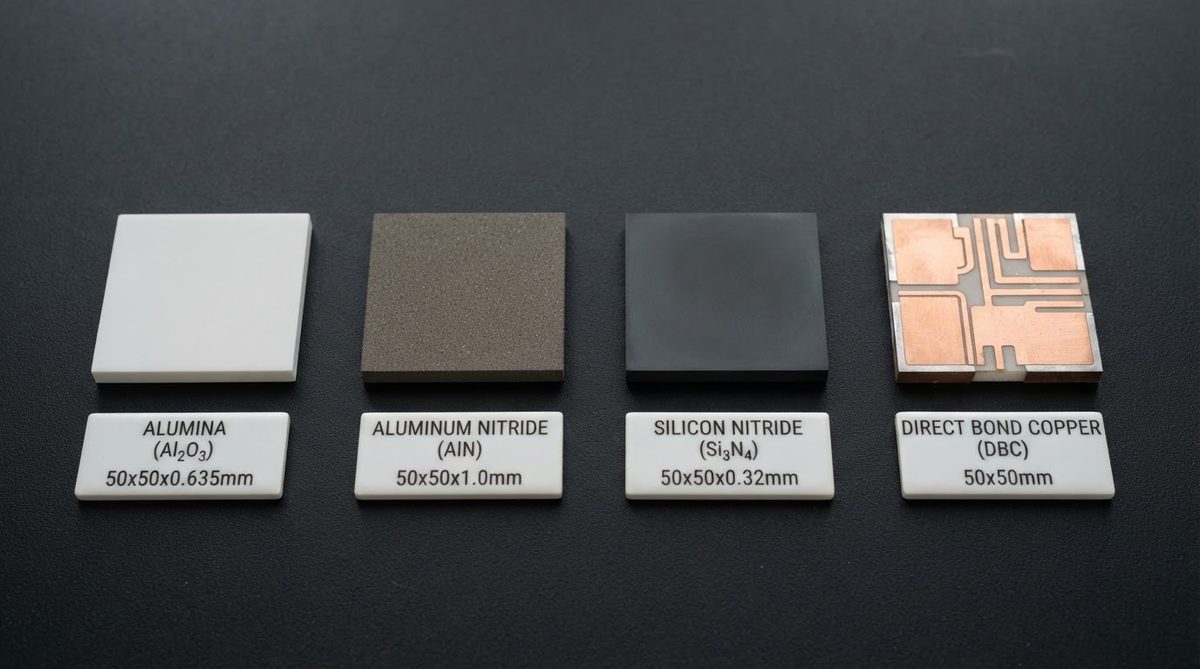
- Material selection within ceramics matters: 96% Al₂O₃ at roughly $0.15–0.40/cm² is far cheaper than AlN at $1.50–4.00/cm² or Si₃N₄ at $3–8/cm².
Why Ceramic Boards Cost More Up Front
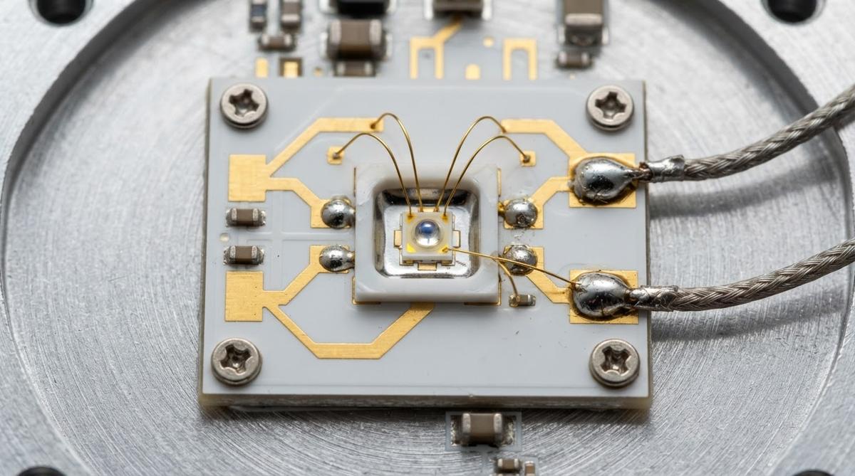
The raw substrate is the main driver. Alumina (Al₂O₃ 96%) powder must be sintered above 1,500 °C; aluminum nitride (AlN) above 1,750 °C in a nitrogen atmosphere. Metallization adds another cost layer—DBC (direct bond copper), DPC (direct plated copper), and thick-film processes each carry different tooling and per-unit charges. FR-4 lamination, by contrast, happens at roughly 180 °C with commodity glass-epoxy prepreg.
Tooling amortization hits harder on small runs. A thick-film screen set may cost $300–800, spread over 50 prototypes versus 50,000 production units. For a detailed look at every line item, see the complete ceramic PCB cost breakdown.
Is Ceramic PCB Worth the Cost on a TCO Basis?
Comparing board price alone is like comparing tire prices without factoring fuel economy and tread life. To determine whether ceramic PCB is worth the cost for your project, you need to capture everything from procurement through end-of-life warranty expense.
TCO Components to Quantify
| Cost element | FR-4 / MCPCB baseline | Ceramic impact |
|---|---|---|
| Bare board | $0.02–0.08/cm² | 5–50× higher |
| Heatsink / thermal interface | $0.50–5.00 per assembly | Often eliminated entirely |
| Assembly yield loss | ~0.5–2% (standard) | May increase 1–3% due to handling (brittle) |
| Field failure rate (thermal) | Baseline | 2–10× lower in high-temp apps |
| Warranty / replacement cost | Baseline | Reduced proportionally to failure rate |
| Product footprint | Baseline | 10–40% smaller when heatsink is removed |
| Regulatory qualification | Baseline | Faster for medical, aerospace (proven reliability data) |
Figures are order-of-magnitude ranges for comparison. Your actual numbers depend on volume, material grade, and application.
Enter your substrate dimensions, power dissipation, and operating temperature below to see how thermal derating affects your design margin and whether the ceramic premium is justified.
Worked Example: 20 W LED Module
Consider a UV-C LED module dissipating 20 W across a 25 × 25 mm footprint (3.2 W/cm²). Two options:
Option A — FR-4 + aluminum heatsink: Board $0.45. Thermal interface material $0.30. Machined heatsink $2.80. Total thermal path: board (0.25 W/mK through 1.6 mm) + TIM + heatsink. Junction-to-case thermal resistance ≈ 18 °C/W through the PCB alone. Assembly adds a fastener step. Estimated module cost: $4.55.
Option B — 96% Al₂O₃ DPC ceramic, 0.635 mm thick: Board $1.90. No heatsink (module bolts directly to chassis). Thermal resistance through substrate ≈ 1.0 °C/W (k = 25 W/mK, area 6.25 cm², thickness 0.635 mm). Estimated module cost: $2.40, with a 17 °C lower junction temperature.
Option B costs 47% less at the module level and runs cooler, extending LED lumen maintenance. In this scenario, asking whether ceramic PCB is worth the cost answers itself—the ceramic option is both cheaper and thermally superior at the assembly level.
Five Applications Where Ceramic Typically Pays for Itself
1. Power Electronics and SiC/GaN Modules
SiC MOSFETs switch at junction temperatures of 175–200 °C. FR-4 has a Tg of 130–180 °C and degrades rapidly above it. A ceramic substrate (Al₂O₃ or AlN with DBC copper) eliminates the organic weak link and matches the CTE of the SiC die (4.0–4.5 ppm/°C for AlN vs. 4.0 ppm/°C for SiC). The cost premium is dwarfed by the avoided thermal derating and warranty returns on a $50–500 power module.
2. Medical Implants and Instruments
Ceramic is biocompatible, withstands autoclave sterilization (134 °C, 2 atm), and meets the hermeticity requirements of implantable devices. The regulatory cost of qualifying a cheaper material that fails in the field far exceeds the substrate premium. See ceramic PCB application areas for qualification-specific context.
3. High-Frequency and mmWave RF
Al₂O₃ 99.6% has a dielectric constant of 9.8–10.0 with a loss tangent below 0.0002 at 10 GHz (per CoorsTek ADS-996 datasheet). That stability lets you shrink filter and antenna footprints while holding impedance tolerance. The alternative—Rogers or Taconic RF laminates—costs nearly as much per cm² anyway.
4. Laser Diode Submounts
A laser diode dissipating 3–10 W in a 1 × 2 mm footprint needs a submount with thermal conductivity above 150 W/mK and CTE near 4–6 ppm/°C. AlN meets both. No organic substrate comes close. The submount cost is a small fraction of the $20–200 laser diode it protects.
5. Harsh-Environment Industrial Sensors
Downhole oil-and-gas sensors, exhaust-gas sensors, and aerospace proximity sensors routinely exceed 200 °C ambient. Ceramic substrates operate continuously at 300–350 °C (Al₂O₃) or beyond, where every organic laminate has long since decomposed. For temperature limits by material grade, see ceramic PCB maximum operating temperature.
When Ceramic Is NOT Worth It
Ceramic is the wrong choice—and a waste of budget—in these situations:
- Low power density below ~1 W/cm². Standard FR-4 or metal-core PCB handles the heat at a fraction of the cost.
- Large board area with simple routing. A 200 × 300 mm control board with through-hole connectors gains nothing from ceramic and would cost 20–100× more.
- High mechanical shock or flex. Ceramic fractures under bending. If the product is dropped, vibrated aggressively, or flexed during use, a polyimide flex or reinforced FR-4 is more appropriate.
- Consumer electronics with 2–3 year design life. The long-term reliability advantage of ceramic has no time to pay back if the product is obsolete in two years.
- Prototyping general logic circuits. Use FR-4 for functional validation, then move to ceramic only for the thermal-critical sub-assembly.
If you are on the fence, strategies for reducing ceramic PCB cost—panel optimization, material-grade selection, and volume consolidation—can shift the breakeven point in ceramic’s favor.
A Quick Decision Framework
Answer these four questions about your design. If you get three or more “yes” answers, ceramic PCB is worth the cost at the TCO level for most projects.
- Does the hottest component dissipate more than 3 W/cm² at the board interface?
- Will the board operate above 150 °C ambient, or survive repeated thermal cycles beyond the Tg of FR-4?
- Does the application require CTE matching within 2 ppm/°C of a die or package?
- Is the end product’s unit value above $50, making field failure costs significant?
Material Grade Matters for ROI
Choosing the cheapest ceramic that meets your thermal and electrical requirements is the single biggest lever on whether ceramic PCB is worth the cost. Do not default to AlN when 96% alumina will do.
| Material | Thermal conductivity (W/mK) | Approx. substrate cost ($/cm²) | Best fit |
|---|---|---|---|
| Al₂O₃ 96% | 24–28 | 0.15–0.40 | General thermal, RF, LED |
| Al₂O₃ 99.6% | 28–35 | 0.30–0.80 | Precision RF, high-purity |
| AlN | 170–200 | 1.50–4.00 | Power modules, laser submounts |
| Si₃N₄ | 70–90 | 3.00–8.00 | High-reliability power cycling |
Typical values for commercially available material, for comparison only. Confirm against the datasheet for your specific grade. Cost ranges reflect 2024 market pricing at moderate volumes; see ceramic substrate material options for detail on each grade.
FAQ
How much more does a ceramic PCB cost than FR-4?
Bare board cost is typically 5–50× higher, depending on material grade, metallization process, and board size. However, total module cost can be lower once heatsinks and thermal interface materials are removed from the bill of materials.
Can I use ceramic for just the thermal sub-assembly and FR-4 for the rest?
Yes, and this is common practice. A small ceramic substrate carrying the power die or LED is soldered or bonded onto a larger FR-4 motherboard. This hybrid approach captures the thermal benefit where it matters without paying the ceramic premium across the entire product.
Does ceramic PCB reduce warranty costs?
In thermally stressed applications, yes. Ceramic substrates do not delaminate, outgas, or degrade at high temperatures the way organic laminates do. Field failure rates in power and LED modules are routinely 2–10× lower on ceramic, per published reliability data from Infineon and Wolfspeed application notes.
What is the minimum order quantity for ceramic PCBs?
Most manufacturers offer prototype quantities starting at 1–25 pieces, though per-unit cost is significantly higher than production runs. Tooling charges (screens, masks) are amortized across the order, so cost per board drops steeply between 10 and 1,000 units.
Is ceramic PCB worth it for a product that ships fewer than 1,000 units per year?
Often yes, provided the unit value is high enough. Medical devices, aerospace sensors, and industrial power modules frequently ship in hundreds per year and justify ceramic on reliability and qualification grounds alone. The key metric is not volume—it is the cost of a single field failure relative to the substrate premium.
Next Step
Map your hottest component’s power density and operating temperature against the decision framework above. If ceramic fits, request a quote with your specific dimensions, material grade, and annual volume to get an accurate per-unit price. You can start a ceramic PCB cost estimate here.