A led star board ceramic substrate can cut junction-to-board thermal resistance to 0.5–2.0 °C/W, compared with 3–10 °C/W for a typical aluminum MCPCB star board. That difference translates directly into lower junction temperature, higher lumen maintenance, and longer LED life. The trade-off is cost: a led star board ceramic option runs roughly 3–8× the price of an equivalent MCPCB, so the choice depends on your thermal budget, reliability target, and production volume.
Key Takeaways
- 96% alumina (Al₂O₃) star boards deliver 24–28 W/m·K bulk thermal conductivity versus 1.0–2.2 W/m·K for the dielectric layer in an aluminum MCPCB.
- Aluminum nitride (AlN) star boards reach 170–200 W/m·K, making them viable for LED packages dissipating 10 W or more per die.
- Ceramic’s CTE (6.5–7.0 ppm/°C for Al₂O₃) is a closer match to GaN-on-SiC LED dies (~4.5 ppm/°C) than aluminum MCPCB (~23 ppm/°C), reducing solder-joint fatigue.
- For LEDs under 3 W per die in non-critical applications, MCPCB is usually the more cost-effective choice.
- Ceramic substrates are brittle; automated pick-and-place handling and fixture design must account for this.
What Is a LED Star Board Ceramic Substrate?
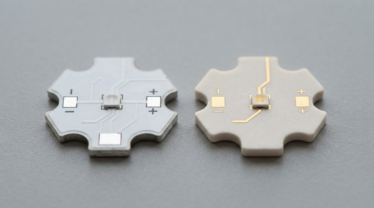
An LED star board is a small substrate, typically 20–25 mm in diameter, shaped as a circle or hexagon with a central thermal pad and radial electrical traces. It carries one or a few high-power LED packages and bolts onto a heatsink. The star shape standardizes mechanical mounting and simplifies optics alignment in luminaire assemblies.
Star boards are made from either metal-core PCB (MCPCB) or ceramic. When engineers specify a led star board ceramic option, they choose a substrate where the entire body is the dielectric—eliminating the thin, thermally resistive polymer layer that limits MCPCB performance. The substrate choice controls the dominant thermal resistance between the LED junction and the heatsink, which in turn governs peak junction temperature and lumen depreciation rate.
Thermal Performance of LED Star Board Ceramic vs MCPCB
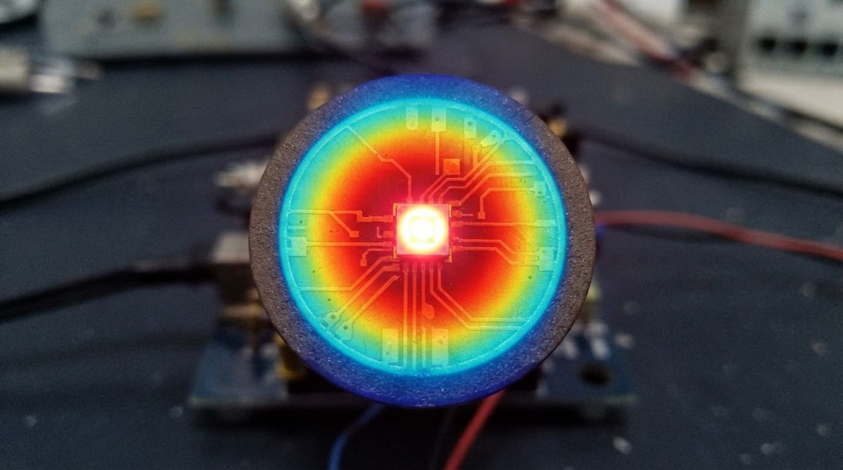
The thermal bottleneck in an MCPCB star board is the dielectric layer between the copper circuit and the aluminum base. Even “high-performance” dielectrics rarely exceed 2.2 W/m·K. At a typical thickness of 75 µm, that dielectric contributes roughly 0.34 °C/W per cm² of pad area. In a ceramic board, the entire substrate is the dielectric, and its bulk conductivity is the relevant number. For 96% Al₂O₃ at 0.635 mm thick, the equivalent figure is about 0.023 °C/W per cm²—an order of magnitude lower.
Worked Example: 5 W LED on a 20 mm Star Board
Assume a single 5 W LED with a 4 × 4 mm thermal pad mounted on a 20 mm-diameter star board, bolted to an infinite heatsink through thermal grease (RTIM ≈ 0.2 °C/W).
MCPCB path (1.6 W/m·K dielectric, 75 µm thick):
Rdielectric = 0.075 m / (1.6 W/m·K × 0.00016 m²) = 0.29 °C/W (pad area only, no spreading).
Total Rboard ≈ 0.29 + 0.2 (TIM) = 0.49 °C/W. ΔT above heatsink = 5 × 0.49 ≈ 2.5 °C.
Al₂O₃ 96% path (25 W/m·K, 0.635 mm thick):
Rsubstrate = 0.000635 / (25 × 0.00016) = 0.16 °C/W.
Total Rboard ≈ 0.16 + 0.2 = 0.36 °C/W. ΔT above heatsink = 5 × 0.36 ≈ 1.8 °C.
At 5 W, the difference is modest—about 0.7 °C. Scale to a 15 W COB LED or a tight cluster, and the gap widens to 5–15 °C, which can mean the difference between meeting and missing a 50,000-hour L70 target. For COB arrays above 10 W, an alumina and AlN material comparison shows why AlN substrates become worth evaluating.
Enter your substrate area, thickness, and dissipated power below to estimate junction temperature rise for your own led star board ceramic design.
CTE Mismatch and Solder-Joint Reliability
High-power LEDs cycle between ambient and 80–120 °C at the solder joint. Every cycle stresses the solder because the substrate and the LED package expand at different rates. Aluminum MCPCB has a CTE around 23 ppm/°C. A typical alumina ceramic sits at 6.5–7.0 ppm/°C (per CoorsTek ADS-96R datasheet, 25–300 °C). GaN-on-sapphire LED dies are roughly 5.0–7.5 ppm/°C depending on orientation.
The closer CTE match between a led star board ceramic substrate and the LED die reduces shear strain per cycle. In accelerated thermal cycling tests (JEDEC JESD22-A104, –40 to +125 °C), ceramic-mounted LEDs routinely survive 2–3× more cycles before solder-joint failure than MCPCB-mounted equivalents. This matters most in outdoor and automotive luminaires where daily thermal cycles accumulate over 10+ years.
Reflectivity and Optical Efficiency
White-body 96% alumina substrates offer diffuse reflectance of 85–92% in the visible spectrum without any added coating. Aluminum MCPCB solder mask is typically white, but reflectance is 75–85% and degrades with UV exposure and heat over time. For luminaires where every percentage point of extraction efficiency matters—surgical lighting, UV curing—ceramic’s stable reflectance is a real advantage. If surface finish is a design factor, the choice between as-fired and polished ceramic finishes affects both reflectance uniformity and solder-paste printing.
Comparison Table: LED Star Board Ceramic vs MCPCB
| Parameter | 96% Al₂O₃ Ceramic | AlN Ceramic | Aluminum MCPCB | Unit | Condition / Source |
|---|---|---|---|---|---|
| Bulk thermal conductivity | 24–28 | 170–200 | 1.0–2.2 (dielectric only) | W/m·K | 20 °C; CoorsTek / Maruwa datasheets |
| CTE | 6.5–7.0 | 4.4–4.7 | ~23 | ppm/°C | 25–300 °C |
| Dielectric strength | ≥ 15 | ≥ 14 | 3–6 (dielectric layer) | kV/mm | ASTM D149 |
| Visible reflectance (white body) | 85–92 | 60–70 (gray body) | 75–85 (white mask) | % | 400–700 nm range |
| Max continuous temperature | 1 000+ | 1 000+ | 130–150 (dielectric limit) | °C | Manufacturer rating |
| Relative cost (per star board) | 3–5× | 8–12× | 1× (baseline) | — | Typical 20 mm, qty 1 000 |
Typical values for commercially available material, for comparison only. Confirm against the datasheet for your specific grade.
When NOT to Use a Ceramic Star Board
Ceramic is overkill—and an unnecessary cost—in several common scenarios:
- Low-power indicator LEDs (≤ 1 W). Thermal load is trivial. Standard FR-4 or single-layer MCPCB handles it fine.
- High-volume consumer lighting (≤ 3 W/die) with a 25,000-hour L70 target. MCPCB meets the thermal budget at a fraction of the cost. A detailed ceramic versus metal-core PCB comparison can help you confirm the boundary for your specific design.
- Large-format boards. Ceramic substrates are limited in panel size and are fragile at large spans. If your design exceeds ~50 mm, MCPCB or IMS is usually more practical.
- Cost-driven retrofit lamps. The luminaire selling price will not support a ceramic substrate.
Choosing the Right Ceramic Grade for Your LED Star Board
96% alumina is the default for most led star board ceramic designs. It balances thermal performance, white-body reflectance, and cost. Move to 99.6% alumina only if you need tighter dimensional tolerance or slightly higher conductivity (~30–33 W/m·K). Move to AlN only when per-die dissipation exceeds ~10 W and junction temperature is the binding constraint. Understanding the thermal management options for ceramic substrates helps clarify that “ceramic” is a family of materials, not a single spec.
Frequently Asked Questions
Can I reflow solder an LED directly onto a ceramic star board?
Yes. Ceramic star boards with metallized pads (DPC copper, thick-film silver, or thin-film gold) are fully compatible with standard SAC305 reflow profiles up to 260 °C peak. The ceramic itself tolerates well over 1 000 °C, so the substrate is never the thermal limit during reflow.
Do ceramic star boards need a separate heatsink?
Almost always, yes. The ceramic substrate reduces thermal resistance between the LED and the mounting surface, but it does not replace a heatsink. You still need a thermal path from the board’s back side to ambient air, typically via a metal heatsink and thermal interface material.
How do I attach a ceramic star board to a heatsink?
The most common methods are thermal adhesive, thermal grease with a mechanical clamp, or soldering the board’s back-side metallization directly to a metal slug. Direct soldering gives the lowest interface resistance but requires a metallized back side and careful CTE management.
Will a led star board ceramic substrate crack during thermal cycling?
Ceramic is brittle, but standard LED thermal cycles (–40 to +125 °C) do not generate enough stress to crack a properly mounted 0.25–1.0 mm alumina substrate. Cracking usually results from mechanical point loading—overtorqued screws, uneven heatsink surfaces, or impact during handling—not from thermal cycling itself.
Is AlN better than alumina for every LED application?
No. AlN has a gray body that reflects only 60–70% of visible light, compared with 85–92% for white alumina. In applications where optical efficiency matters more than raw thermal conductivity, 96% alumina outperforms AlN on a system level despite its lower thermal conductivity.
What is the typical lead time for ceramic LED star boards?
Prototype quantities (10–50 pcs) typically ship in 2–4 weeks from most ceramic PCB fabricators. Production runs of 1 000+ pieces take 3–6 weeks depending on metallization process and ceramic PCB pricing factors. MCPCB star boards are generally 1–2 weeks faster at both stages.