What is a Two Layer PCB?
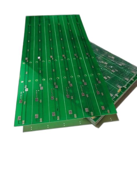
A two layer PCB, also known as a double-sided PCB, consists of a substrate material with conductive copper layers on both sides. The copper layers are etched with the desired circuit pattern, and the components are mounted on one or both sides of the board. Two layer PCBs offer several advantages over single-sided PCBs, including:
- Increased circuit density and complexity
- Better signal integrity and noise reduction
- Improved mechanical strength and durability
Materials Used in Two Layer PCB Fabrication
The choice of materials is crucial in ensuring the quality and reliability of a two layer PCB. The most common materials used in PCB fabrication include:
Substrate Material
The substrate is the foundation of the PCB, providing mechanical support and electrical insulation. The most commonly used substrate materials for two layer PCBs are:
- FR-4: A composite material made of fiberglass and epoxy resin, offering excellent electrical insulation and mechanical strength.
- CEM-1: A composite material made of cotton paper and epoxy resin, providing a cost-effective alternative to FR-4 for less demanding applications.
Copper Foil
The conductive layers of a two layer PCB are made of copper foil, which is laminated onto the substrate. The thickness of the copper foil is typically measured in ounces per square foot (oz/ft²), with common thicknesses being 0.5 oz/ft², 1 oz/ft², and 2 oz/ft².
Solder Mask
A solder mask is a protective layer applied over the copper traces, leaving only the areas intended for soldering exposed. The solder mask helps prevent short circuits and improves the PCB’s appearance. Green is the most common color for solder masks, but other colors like red, blue, and black are also available.
Silkscreen
The silkscreen layer is used to print text, logos, and component identifiers on the PCB’s surface. This layer helps in the assembly process and makes it easier to identify components and their orientation. White is the most common color for silkscreen, but other colors can be used for better contrast or aesthetic purposes.

Two Layer PCB Fabrication Process
The fabrication of a two layer PCB involves several steps, each requiring precision and attention to detail. The main steps in the process are:
1. Design and Gerber File Generation
The PCB design is created using electronic design automation (EDA) software, such as Altium Designer, KiCad, or Eagle. The design includes the schematic, component placement, and routing of the copper traces. Once the design is finalized, Gerber files are generated, which contain the necessary information for each layer of the PCB.
2. Copper Clad Laminate Preparation
The substrate material, typically FR-4 or CEM-1, is cut to the desired size and shape. Copper foil is then laminated onto both sides of the substrate using heat and pressure. The thickness of the copper foil depends on the specific requirements of the PCB.
3. Drilling
Holes are drilled through the copper-clad laminate to accommodate through-hole components and vias. The drilling process is carried out using computer numerical control (CNC) machines, ensuring precise hole placement and size.
4. Copper Patterning
The desired circuit pattern is transferred onto the copper layers using a photolithographic process. This involves the following steps:
a. Photoresist Application: A light-sensitive polymer, called photoresist, is applied evenly onto the copper surfaces.
b. Exposure: The photoresist-coated laminate is exposed to ultraviolet (UV) light through a photomask, which contains the circuit pattern. The exposed areas of the photoresist become soluble.
c. Developing: The exposed laminate is immersed in a developing solution, which removes the soluble photoresist, revealing the desired circuit pattern.
d. Etching: The developed laminate is placed in an etching solution, typically ferric chloride or ammonium persulfate, which removes the unprotected copper, leaving only the desired circuit pattern.
e. Photoresist Removal: The remaining photoresist is stripped away using a chemical solution, revealing the etched copper pattern.
5. Solder Mask Application
A solder mask layer is applied over the etched copper layers, leaving only the areas intended for soldering exposed. The solder mask is typically applied using a silkscreen printing process, followed by a curing step to harden the mask.
6. Surface Finish
A surface finish is applied to the exposed copper areas to protect them from oxidation and improve solderability. Common surface finishes for two layer PCBs include:
- Hot Air Solder Leveling (HASL): A thin layer of solder is applied to the exposed copper using a hot air leveling machine.
- Electroless Nickel Immersion Gold (ENIG): A layer of nickel is deposited onto the copper, followed by a thin layer of gold.
- Immersion Silver: A thin layer of silver is deposited onto the copper through a chemical process.
7. Silkscreen Application
The silkscreen layer, containing text, logos, and component identifiers, is applied onto the PCB’s surface using a silkscreen printing process. The ink used for silkscreening is typically epoxy-based and requires a curing step to ensure durability.
8. Electrical Testing
The fabricated PCBs undergo electrical testing to ensure they meet the specified requirements and are free from defects. This may include:
- Continuity Testing: Verifying that the electrical connections between points on the PCB are intact.
- Insulation Resistance Testing: Measuring the resistance between isolated conductors to ensure proper insulation.
- High-Voltage Testing: Applying a high voltage between conductors to detect any potential leakage or breakdown in insulation.

Quality Control in Two Layer PCB Fabrication
Ensuring the quality of two layer PCBs is essential for their reliable performance in electronic devices. Quality control measures are implemented throughout the fabrication process, including:
- Visual Inspection: PCBs are visually inspected for defects such as scratches, dents, or discoloration.
- Automated Optical Inspection (AOI): An automated system captures images of the PCB and compares them to a reference design to detect any discrepancies or defects.
- X-ray Inspection: X-ray imaging is used to inspect the internal structure of the PCB, detecting any voids or defects in the plated through-holes.
- Impedance Control: For high-speed or high-frequency applications, the impedance of the PCB traces is controlled to ensure signal integrity.
- Dimensional Verification: The physical dimensions of the PCB, including thickness, hole size, and feature locations, are verified using precision measuring equipment.

Advantages of Two Layer PCBs
Two layer PCBs offer several advantages over single-sided PCBs, making them a popular choice for a wide range of applications:
-
Increased Circuit Density: With copper layers on both sides of the substrate, two layer PCBs can accommodate more components and complex routing in a smaller footprint.
-
Better Signal Integrity: The use of a dedicated ground plane on one side of the PCB helps reduce electromagnetic interference (EMI) and improves signal integrity.
-
Enhanced Mechanical Strength: The additional copper layer and the bonding between layers provide increased mechanical strength and durability compared to single-sided PCBs.
-
Cost-Effective: Two layer PCBs offer a balance between cost and performance, making them a cost-effective solution for many applications that require more complexity than single-sided PCBs but do not need the advanced features of multilayer PCBs.
Applications of Two Layer PCBs
Two layer PCBs find applications in a wide range of industries and products, such as:
- Consumer Electronics: Smartphones, tablets, laptops, and wearable devices.
- Automotive Electronics: Infotainment systems, engine control units, and sensors.
- Industrial Control Systems: Programmable logic controllers (PLCs), human-machine interfaces (HMIs), and sensor networks.
- Medical Devices: Patient monitors, diagnostic equipment, and portable medical devices.
- Telecommunications: Routers, switches, and modems.
- Aerospace and Defense: Avionics systems, communication equipment, and surveillance devices.
Frequently Asked Questions (FAQ)
-
Q: What is the difference between a two layer PCB and a multilayer PCB?
A: A two layer PCB has copper layers on both sides of the substrate, while a multilayer PCB has additional layers sandwiched between the top and bottom layers. Multilayer PCBs offer higher circuit density and better signal integrity but are more complex and expensive to manufacture. -
Q: Can two layer PCBs have plated through-holes?
A: Yes, two layer PCBs can have plated through-holes, which are holes that are electrically connected to the copper layers on both sides of the board. This allows for the use of through-hole components and provides electrical continuity between the layers. -
Q: What is the typical turnaround time for two layer PCB fabrication?
A: The turnaround time for two layer PCB fabrication depends on various factors, such as the complexity of the design, the quantity ordered, and the chosen manufacturing service. Typical turnaround times can range from a few days to a couple of weeks. -
Q: Can two layer PCBs be used for high-frequency applications?
A: Two layer PCBs can be used for high-frequency applications, but their performance may be limited compared to multilayer PCBs. For demanding high-frequency applications, multilayer PCBs with dedicated power and ground planes and controlled impedance traces are often preferred. -
Q: What is the minimum feature size achievable in two layer PCB fabrication?
A: The minimum feature size in two layer PCB fabrication depends on the capabilities of the manufacturing facility. Typical minimum feature sizes range from 0.1 mm to 0.2 mm (4 to 8 mils) for trace width and spacing. However, some advanced facilities may offer even smaller feature sizes.
Conclusion
Two layer PCB fabrication is a complex process that involves multiple steps, materials, and quality control measures. By understanding the fabrication process and the advantages of two layer PCBs, designers and engineers can make informed decisions when selecting the appropriate PCB technology for their applications. As electronics continue to evolve, the demand for high-quality, cost-effective two layer PCBs will remain strong, driving innovations in materials, manufacturing techniques, and design tools.
| Comparison | Two Layer PCBs | Multilayer PCBs |
|---|---|---|
| Number of Copper Layers | 2 (top and bottom) | 3 or more |
| Circuit Density | Moderate | High |
| Signal Integrity | Good, with dedicated ground plane | Excellent, with power and ground planes |
| Mechanical Strength | Good | Excellent |
| Cost | Lower | Higher |
| Typical Applications | Consumer electronics, automotive, industrial | High-performance electronics, aerospace, medical devices |
Table: Comparison between Two Layer and Multilayer PCBs
By carefully considering the requirements of their application and the capabilities of two layer PCB fabrication, designers can create reliable, cost-effective electronic devices that meet the demands of today’s rapidly evolving technology landscape.


Leave a Reply