Introduction to Microcontroller Circuits
A microcontroller is a small, self-contained computer that is designed to control a specific task or set of tasks. It is a type of integrated circuit that contains a processor, memory, and input/output peripherals, all on a single chip. Microcontrollers are widely used in embedded systems, such as home appliances, automotive electronics, and industrial control systems.
Creating a microcontroller circuit board involves several steps, including selecting the appropriate microcontroller, designing the circuit schematic, laying out the printed circuit board (PCB), and assembling the components. In this article, we will guide you through the process of creating a microcontroller circuit board, from start to finish.
Choosing the Right Microcontroller
The first step in creating a microcontroller circuit board is to select the appropriate microcontroller for your project. There are many different types of microcontrollers available, each with its own set of features and capabilities. Some of the most popular microcontroller families include:
- Arduino
- PIC
- AVR
- ARM
When choosing a microcontroller, you should consider factors such as:
- Processing power
- Memory capacity
- Number of input/output pins
- Analog-to-digital conversion (ADC) capabilities
- Communication interfaces (e.g., UART, I2C, SPI)
- Power consumption
- Cost
Microcontroller Comparison Table
| Microcontroller Family | Processing Power | Memory Capacity | I/O Pins | ADC | Communication Interfaces | Power Consumption | Cost |
|---|---|---|---|---|---|---|---|
| Arduino | Low to Medium | Low to Medium | Medium | Yes | UART, I2C, SPI | Low to Medium | Low |
| PIC | Low to High | Low to High | Low to High | Yes | UART, I2C, SPI, USB | Low to High | Low to Medium |
| AVR | Low to High | Low to High | Medium to High | Yes | UART, I2C, SPI, USB | Low to Medium | Low to Medium |
| ARM | Medium to High | Medium to High | High | Yes | UART, I2C, SPI, USB, Ethernet | Low to High | Medium to High |

Designing the Circuit Schematic
Once you have selected the appropriate microcontroller for your project, the next step is to design the circuit schematic. The circuit schematic is a diagram that shows how the components in your circuit are connected together.
When designing the circuit schematic, you should consider the following:
- Power supply requirements
- Input/output connections
- External components (e.g., sensors, actuators, displays)
- Communication interfaces
- PCB layout considerations
There are many software tools available for designing circuit schematics, such as KiCad, Eagle, and Altium Designer. These tools allow you to create a digital representation of your circuit, which can then be used to generate a PCB layout.
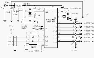
Example Circuit Schematic

Laying Out the Printed Circuit Board (PCB)
After designing the circuit schematic, the next step is to lay out the printed circuit board (PCB). The PCB is the physical board that holds all of the components in your circuit.
When laying out the PCB, you should consider the following:
- Component placement
- Trace routing
- Power and ground planes
- Signal integrity
- Manufacturability
PCB layout software, such as KiCad, Eagle, and Altium Designer, can help you create a PCB layout that meets your design requirements. These tools allow you to place components, route traces, and add power and ground planes to your PCB.
Example PCB Layout

Assembling the Components
Once you have designed the circuit schematic and laid out the PCB, the next step is to assemble the components onto the board. This involves soldering the components onto the PCB and making any necessary connections.
When assembling the components, you should consider the following:
- Soldering techniques
- Component orientation
- Electrostatic discharge (ESD) protection
- Testing and debugging
It is important to follow proper soldering techniques and to double-check your connections to ensure that your circuit functions correctly. You may also need to use specialized tools, such as a multimeter or oscilloscope, to test and debug your circuit.
Soldering Tips
- Use a soldering iron with a fine tip and adjustable temperature control
- Use lead-free solder and flux
- Keep the soldering iron tip clean and tinned
- Hold the soldering iron at a 45-degree angle to the component lead
- Apply heat to the component lead and PCB pad simultaneously
- Apply solder to the joint, not the soldering iron tip
- Allow the joint to cool before moving the component
Testing and Debugging
After assembling the components onto the PCB, the final step is to test and debug your microcontroller circuit. This involves powering up the circuit and verifying that it functions as intended.
When testing and debugging your circuit, you should consider the following:
- Power supply voltage and current
- Input/output functionality
- Communication interfaces
- Sensor and actuator functionality
- Code execution and debugging
If you encounter any issues during testing and debugging, you may need to use specialized tools, such as a logic analyzer or in-circuit debugger, to identify and resolve the problem. It is also important to document any changes or modifications made to the circuit during the debugging process.
Frequently Asked Questions (FAQ)
-
What is a microcontroller?
A microcontroller is a small, self-contained computer that is designed to control a specific task or set of tasks. It contains a processor, memory, and input/output peripherals, all on a single chip. -
How do I choose the right microcontroller for my project?
When choosing a microcontroller, you should consider factors such as processing power, memory capacity, number of input/output pins, analog-to-digital conversion capabilities, communication interfaces, power consumption, and cost. You should also consider the specific requirements of your project and choose a microcontroller that meets those requirements. -
What software tools are used for designing circuit schematics and PCB layouts?
There are many software tools available for designing circuit schematics and PCB layouts, such as KiCad, Eagle, and Altium Designer. These tools allow you to create digital representations of your circuit and PCB, which can then be used for manufacturing. -
What are some common issues encountered when assembling components onto a PCB?
Some common issues encountered when assembling components onto a PCB include improper soldering techniques, incorrect component orientation, electrostatic discharge (ESD) damage, and poor connections. It is important to follow proper soldering techniques and to double-check your connections to ensure that your circuit functions correctly. -
How can I test and debug my microcontroller circuit?
To test and debug your microcontroller circuit, you should power up the circuit and verify that it functions as intended. You may need to use specialized tools, such as a multimeter, oscilloscope, logic analyzer, or in-circuit debugger, to identify and resolve any issues. It is also important to document any changes or modifications made to the circuit during the debugging process.
Conclusion
Creating a microcontroller circuit board involves several steps, including selecting the appropriate microcontroller, designing the circuit schematic, laying out the PCB, assembling the components, and testing and debugging the circuit. By following the guidelines and tips outlined in this article, you can create a functional and reliable microcontroller circuit board for your project.
Remember to choose the right microcontroller for your project requirements, use appropriate software tools for designing the circuit schematic and PCB layout, follow proper soldering techniques when assembling the components, and thoroughly test and debug your circuit before putting it into use.
With the knowledge and skills gained from this article, you are now equipped to create your own microcontroller circuit boards for a wide range of applications, from simple projects to complex embedded systems.


Leave a Reply