What is an ESR Meter?
An ESR (Equivalent Series Resistance) meter is an electronic device used to measure the equivalent series resistance of capacitors. ESR is an important parameter in determining the health and performance of capacitors, especially in high-frequency applications such as power supplies, switching regulators, and audio circuits.
A high ESR value indicates that the capacitor is degrading and may not perform as expected, leading to circuit malfunctions or failures. Therefore, measuring ESR is crucial for troubleshooting, repairing, and maintaining electronic circuits.
Why Build a DIY ESR Meter?
While commercial ESR meters are readily available, building a DIY ESR meter offers several advantages:
-
Cost-effective: Building your own ESR meter can be significantly cheaper than purchasing a commercial one, especially if you already have some of the components on hand.
-
Customization: A DIY ESR meter allows you to customize the design to suit your specific needs, such as measurement range, accuracy, and features.
-
Learning opportunity: Building an ESR meter from scratch provides an excellent opportunity to learn about electronic circuits, components, and measurement techniques.
-
Satisfaction: There’s a sense of accomplishment and satisfaction that comes with building and using your own tools.

How Does an ESR Meter Work?
An ESR meter works by applying a small AC signal to the capacitor under test and measuring the voltage drop across the capacitor’s ESR. The basic principle can be illustrated using the following simplified circuit:
[Insert a simple circuit diagram showing a capacitor, its ESR, and an AC source]
The AC source applies a known current (I) to the capacitor, and the voltage drop (V) across the ESR is measured. Using Ohm’s law, the ESR can be calculated as:
ESR = V / I
In practice, ESR meters use more sophisticated circuits to accurately measure the ESR while minimizing the influence of the capacitor’s reactance and other factors.

Building a DIY ESR Meter
Circuit Design
There are several circuit designs available for DIY ESR meters, ranging from simple analog circuits to more advanced digital designs. Here, we’ll discuss a popular analog design based on the ILC1001 chip.
The ILC1001 is a precision rms-to-dc converter designed for true rms measurements. It can be used to measure the rms value of the AC voltage drop across the capacitor’s ESR, which is then converted to a DC voltage for easy measurement.
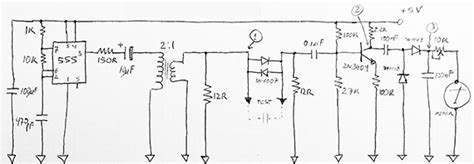
[Insert a schematic diagram of the ILC1001-based ESR meter circuit]
The circuit consists of the following main components:
-
ILC1001 chip: The heart of the ESR meter, responsible for measuring the rms voltage drop across the capacitor’s ESR.
-
AC source: A sine wave generator that provides the AC signal for measuring the ESR. The frequency and amplitude of the signal can be adjusted based on the capacitor’s characteristics.
-
Voltage divider: A resistive voltage divider network that scales the AC signal to an appropriate level for the ILC1001 chip.
-
DC voltage measurement: A digital multimeter (DMM) or an analog voltage meter that measures the DC output voltage from the ILC1001 chip, which is proportional to the ESR.
Component Selection
When building a DIY ESR meter, it’s essential to choose the right components for optimal performance and accuracy. Here are some key considerations:
-
ILC1001 chip: Ensure you have a genuine ILC1001 chip from a reputable supplier. Counterfeit or low-quality chips may lead to inaccurate measurements.
-
Resistors: Use high-precision, low-tolerance resistors (e.g., 1% or better) for the voltage divider network to ensure accurate scaling of the AC signal.
-
Capacitors: Use high-quality, low-ESR capacitors for decoupling and filtering purposes in the circuit. This will help minimize noise and interference.
-
AC source: Choose a stable and low-distortion sine wave generator for the AC source. The frequency and amplitude stability of the source directly impact the accuracy of the ESR measurements.
-
DMM or voltage meter: Use a high-resolution DMM or analog voltage meter with good accuracy and linearity for measuring the DC output voltage from the ILC1001 chip.
PCB Design and Assembly
Once you have finalized the circuit design and selected the components, the next step is to design and fabricate a printed circuit board (PCB) for your DIY ESR meter. A well-designed PCB offers several benefits, such as improved signal integrity, reduced noise, and easier assembly.
Here are some tips for designing and assembling your ESR meter PCB:
-
Use a PCB design software: There are many free and paid PCB design software options available, such as KiCad, Eagle, and Altium Designer. Choose one that suits your needs and skill level.
-
Follow good PCB design practices: Ensure proper grounding, minimize trace lengths, use appropriate trace widths, and provide adequate clearances between components and traces.
-
Consider a double-sided PCB: A double-sided PCB allows for better component placement and routing, which can help improve performance and reduce the overall board size.
-
Use solder masks and silkscreens: Solder masks and silkscreens improve the aesthetics and usability of your PCB, making it easier to assemble and debug.
-
Double-check your design: Before sending your PCB design for fabrication, double-check all connections, component footprints, and design rules to avoid costly mistakes.
-
Choose a reliable PCB Fabrication service: Many online PCB fabrication services offer affordable and high-quality PCBs. Read reviews and compare prices before choosing a service.
-
Use proper soldering techniques: When assembling your PCB, use a temperature-controlled soldering iron, high-quality solder, and follow good soldering practices to ensure reliable connections.
Calibration and Testing
After assembling your DIY ESR meter, it’s crucial to calibrate and test it to ensure accurate and reliable measurements. Here’s a step-by-step guide:
-
Visual inspection: Carefully inspect your assembLED PCB for any soldering defects, short circuits, or damaged components. Address any issues before proceeding.
-
Power-on test: Apply the appropriate power supply to your ESR meter and verify that it powers on without any issues. Check for any abnormal behavior, such as overheating or unexpected voltage levels.
-
AC source calibration: Use an oscilloscope to verify the frequency and amplitude of the AC source. Adjust the source if necessary to match the desired specifications.
-
DC voltage calibration: Apply a known AC signal to the input of the ESR meter and measure the DC output voltage using a calibrated DMM. Compare the measured voltage with the expected value and adjust the circuit if needed.
-
ESR measurement test: Test your ESR meter with a set of capacitors with known ESR values. Compare the measured ESR values with the expected values and verify that the meter is within the acceptable accuracy range.
-
Repeat the calibration and testing process until you are satisfied with the performance and accuracy of your DIY ESR meter.

Using Your DIY ESR Meter
Now that you have a calibrated and tested DIY ESR meter, it’s time to put it to use. Here are some tips for using your ESR meter effectively:
-
Disconnect the capacitor: Always disconnect the capacitor from the circuit before measuring its ESR. In-circuit measurements may lead to inaccurate results due to the influence of other components.
-
Discharge the capacitor: Ensure that the capacitor is fully discharged before connecting it to the ESR meter. Applying the AC signal to a charged capacitor can damage the meter and lead to inaccurate measurements.
-
Connect the capacitor properly: Connect the capacitor to the ESR meter’s test leads, ensuring proper polarity if applicable. Refer to your ESR meter’s documentation for specific connection instructions.
-
Interpret the results: Read the DC voltage from the DMM or analog voltage meter and convert it to ESR using the calibration data or formula specific to your ESR meter design. Compare the measured ESR with the manufacturer’s specifications or typical values for the capacitor type and capacitance.
-
Take multiple measurements: To ensure consistency and reliability, take multiple ESR measurements for each capacitor and average the results.
-
Keep your ESR meter calibrated: Periodically re-calibrate your ESR meter to maintain its accuracy over time. Follow the calibration procedure as described in the previous section.
Troubleshooting and Maintenance
Even with a well-designed and calibrated DIY ESR meter, you may encounter issues or need to perform maintenance tasks. Here are some common troubleshooting and maintenance tips:
-
No power: If your ESR meter doesn’t power on, check the power supply connections, voltage levels, and polarity. Verify that the power supply is providing the correct voltage and current.
-
Inaccurate measurements: If you notice inconsistent or inaccurate ESR measurements, re-calibrate your meter and verify the AC source’s frequency and amplitude. Check for any loose connections or damaged components.
-
Noisy measurements: If your ESR measurements are noisy or unstable, check for any sources of electromagnetic interference (EMI) near your setup. Use shielded cables and keep the ESR meter away from power supplies, motors, and other sources of EMI.
-
Component replacement: If any components in your ESR meter circuit fail or degrade over time, replace them with high-quality equivalents. Regularly inspect your PCB for any signs of damage or wear.
-
Storage and handling: Store your DIY ESR meter in a dry, dust-free environment and handle it with care to prevent damage. Use a protective case or enclosure if necessary.
FAQ
- Can I use my DIY ESR meter to measure other components besides capacitors?
-
No, an ESR meter is specifically designed to measure the equivalent series resistance of capacitors. It cannot accurately measure the resistance of other components like resistors or inductors.
-
What is the typical ESR range for capacitors?
-
The typical ESR range for capacitors varies depending on the capacitor type, capacitance, and voltage rating. Generally, ESR values range from a few milliohms to several ohms. Refer to the manufacturer’s specifications for specific ESR ranges.
-
Can I measure ESR while the capacitor is still in the circuit?
-
No, it is not recommended to measure ESR while the capacitor is still connected in the circuit. The presence of other components can influence the measurement and lead to inaccurate results. Always disconnect the capacitor from the circuit before measuring its ESR.
-
How often should I calibrate my DIY ESR meter?
-
The calibration frequency depends on factors such as usage, environmental conditions, and the stability of the components used in your ESR meter. As a general guideline, consider calibrating your meter at least once every few months or whenever you notice inconsistent or suspicious measurements.
-
Can I use my DIY ESR meter to test high-voltage capacitors?
- No, a DIY ESR meter designed for low-voltage applications should not be used to test high-voltage capacitors. High-voltage capacitors require specialized testing equipment and safety precautions. Always follow the manufacturer’s guidelines and use appropriate equipment when dealing with high-voltage components.
Conclusion
Building a DIY ESR meter is an engaging and rewarding project for electronics enthusiasts. It not only provides a cost-effective solution for measuring the health of capacitors but also offers an excellent learning opportunity.
By following the steps outlined in this article, including circuit design, component selection, PCB design and assembly, calibration, and testing, you can create a reliable and accurate ESR meter for your own use.
Remember to always prioritize safety, follow good engineering practices, and regularly maintain and calibrate your meter for optimal performance.
Happy building and measuring!


Leave a Reply